
Interior
Shift Levers
January 6, 2013
When I was taking the gear shift lever out of the car, I looked at the mechanism for using one lever to control two shift cables. I remember thinking that it was pretty clever. I guess it was done so that the shifting would mimic a transmission that had no cables. Either way, as is common with me, I was just staring at it coming up with ideas (this is one of the reasons I take so long to work on things) and I thought, what if I didn't use one lever. What if I used two levers. That would look really cool. It would be unique and it would also act like a theft deterrant, because no one would know how to drive it.
I spent a lot of time just thinking about whether this could be bad for the transmission. Was there a combination of positions or an order of events that could mess things up? In fact, the transmission itself prevents such a thing. I do believe a reverse lock-out would be good, though. In the Spyder, there is a mechanism that keeps you from putting it in 1st gear unless you are ridiculously close to a full stop and I have accidentally pushed through that. I wouldn't want that to happen on the highway while trying to downshift to 4th or something. That wouldn't be pretty.
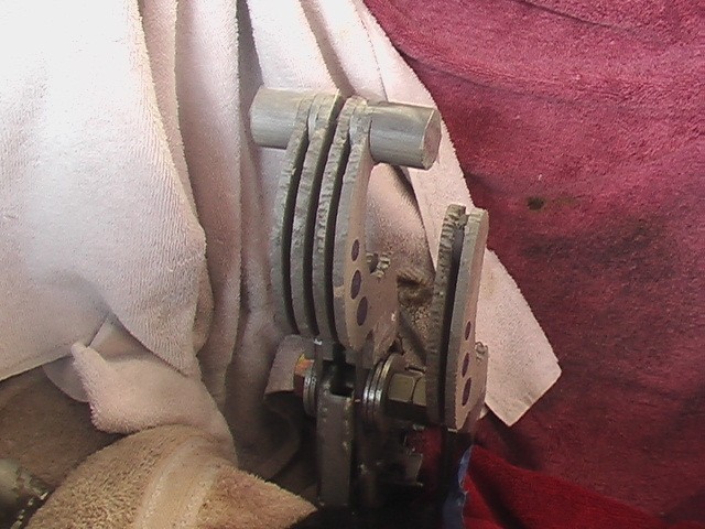
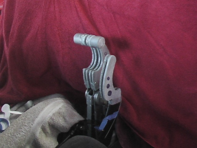
Anyway, the following pictures are my first attempt. I just took a bunch of scrap metal and built a couple of levers, just to get the lengths and positioning right. I thought if the two levers were too close, it might be possible to pinch your hand between them. Also, if the knobs were too small it might be easy to slip off of them. So this was just a mock-up and I figured I would have to make a lot of adjustments. As it turns out, I got it right the first time. . . . That never happens!
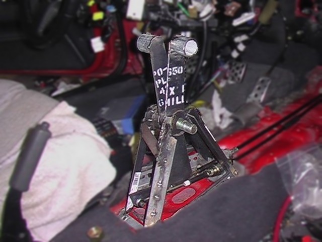
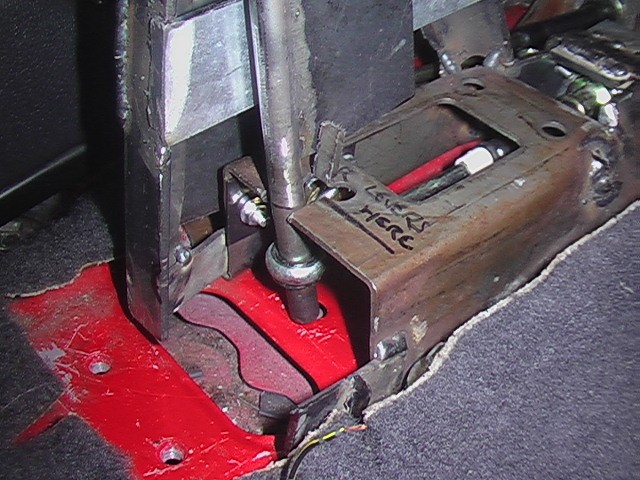
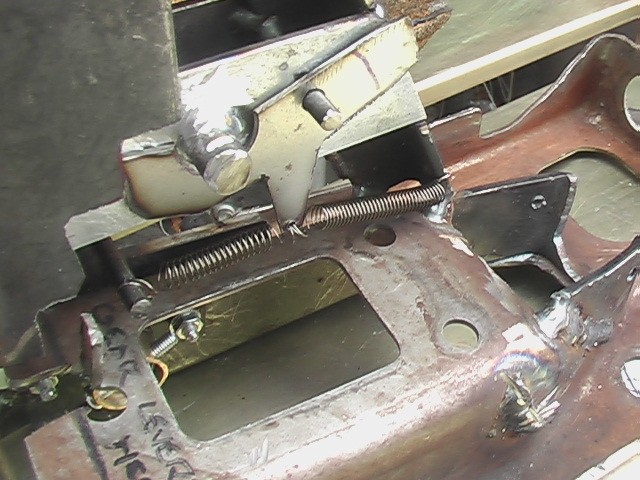
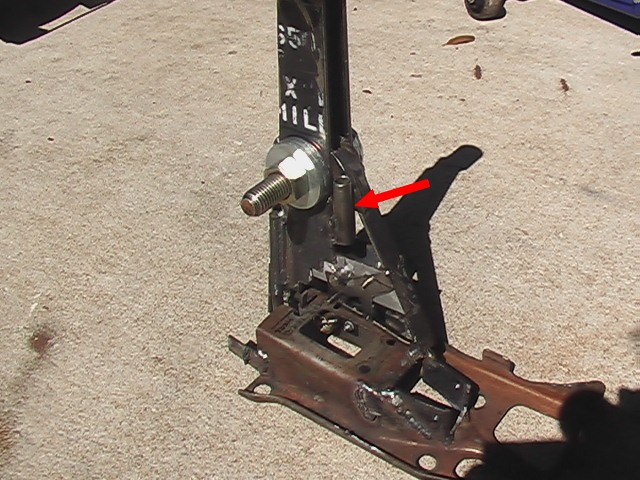
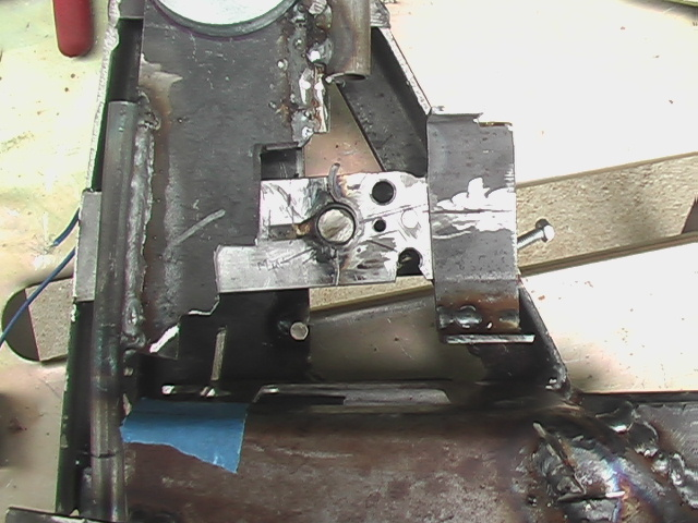
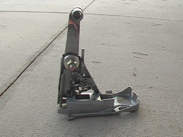
I just built a little frame, cut some levers and drove a 3/4" bolt through the middle for a bearing. I cut two pieces of pipe for the knobs and welded them on. The shift cable ends fit right over a piece of steel rod. I should note, that the left shift cable has a ring shaped end on it and the right one has a sort of cup that acts like a socket for the ball on the end of the shifter. It was easier to use the ring shaped ends so I actually took the left cable out of the Solara and used in the right position of the Corolla. The problem with that is the cables are very stiff and the end wanted to be rotated 90 degrees relative to the left cable. I could force them to be parallel, but I'm afraid it might have put a lot of stress on the twisted cable. So instead I decided to mount the peg that the cable slips over, 90 degrees off from the other one. This will be clearer in future pictures.
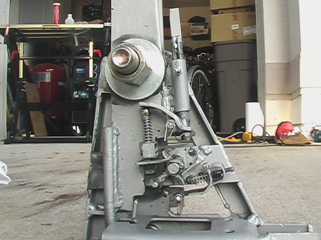
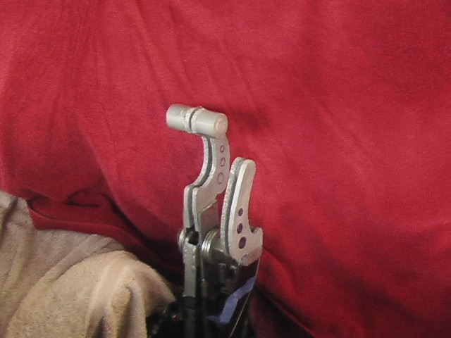
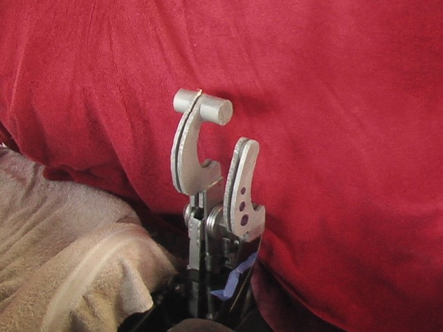
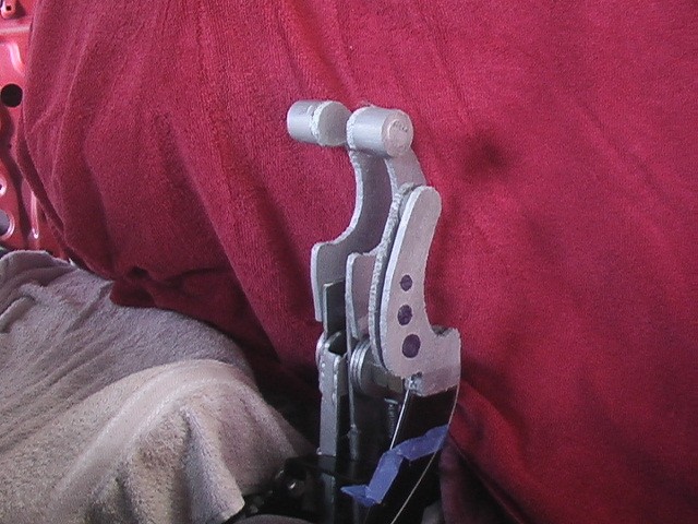
Here are some more pics of the trick twin shift lever set-up. I've enhanced the photos so you can hopefully see it better. And may I just say, I think this may be the coolest thing I have ever done!
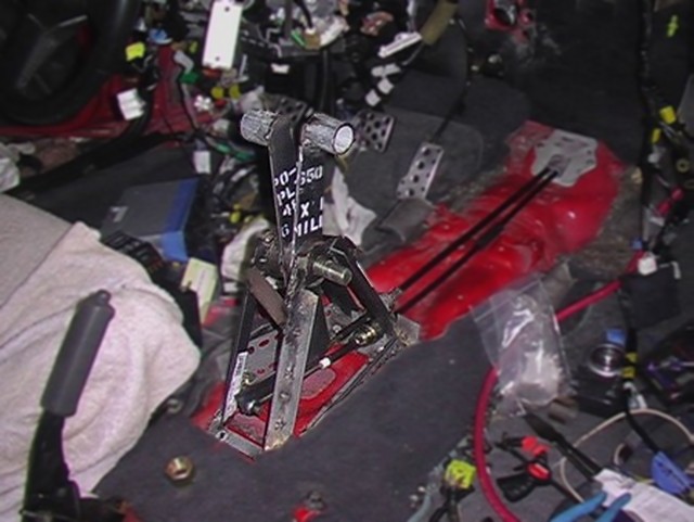
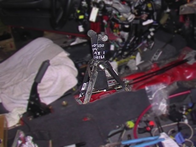
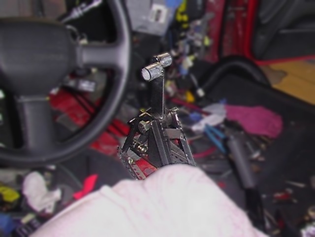
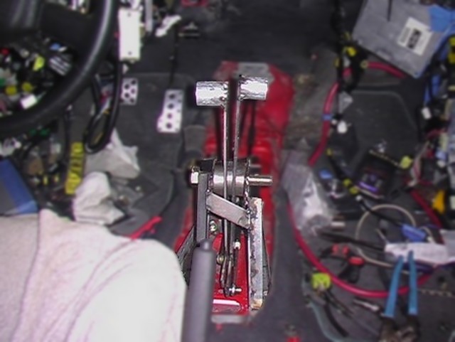
In the above pictures the levers are set in 1st gear. The left lever back and the right lever forward. Once again, this is going to be soooo cool!
December 1, 2013
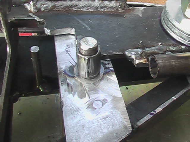
I talked to a mechanical engineer at work and he seemed to think it would be ok, to use the bolt as a bearing. So I took it apart,and welded the structure onto the metal bracket that came with the Corolla. I was careful not to mess it up. With a grinder, I can return it to a one lever shifter if I want to.
I don't want it to look this ugly, but because I may have to make all kinds of adjustments, I decided to leave it ugly below the center console and make it look pretty where you could actually see it. I think this is the best decision, because, to make the levers work, I will have to adjust the pressure on each lever, the location of each lever when it's in neutral and add in a functional reverse lock-out. So I don't want to have a bunch of parts machined and then just have to throw them away or something. If it's just scrap steel, I can do all of those adjustments myself and no one will ever see them anyway.
With that in mind, I designed a few different shift levers (the part that sticks up that people will see. What do you think?
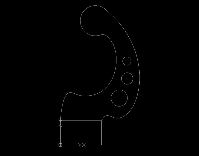
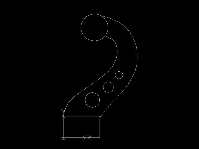

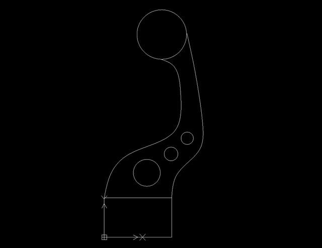
I think I like the first design the best, so I plan to make a mock-up in plastic, before I have anything machined.
If anything the levers need to be just a little bit further away from me in my seating position. The round part on top is not over the center of the flat bottom, which means if I use it one way, the knobs will be a little bit further away from me. But I plan to design them so they can be flipped around. If I do that then, obviously, they would be a little bit closer to me.
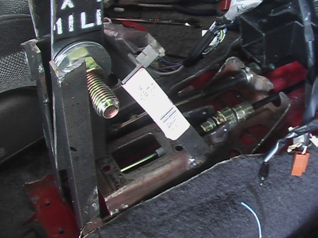
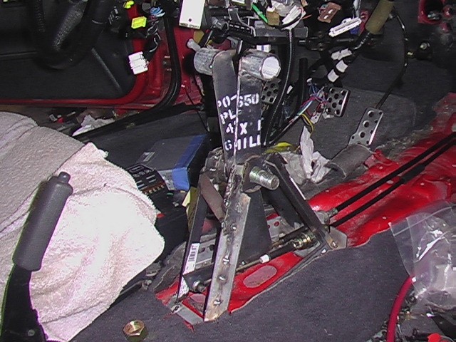
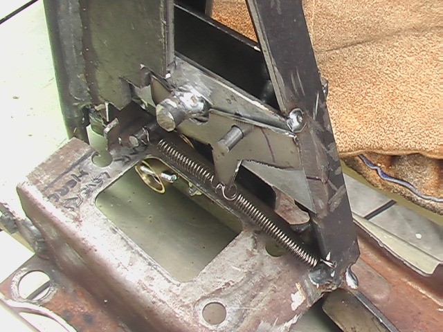
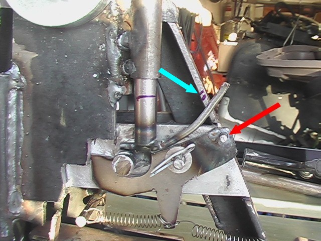
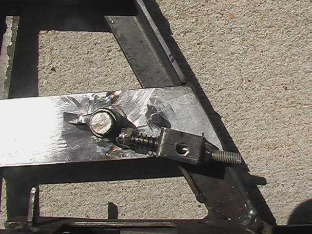
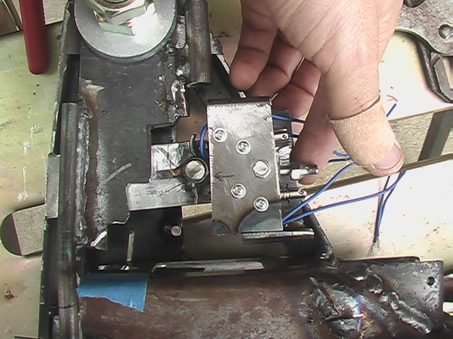
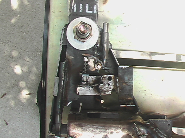
Here I've started building the "permanent" lever mechanism. You can see that it's built on the original Corolla bracket.
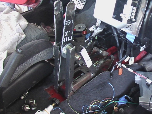
This one will take up a little less room than the other one. The two metal L brackets toward the right get cut off.
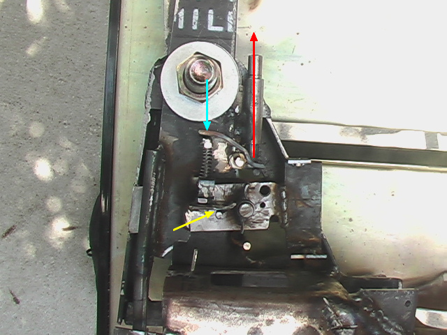
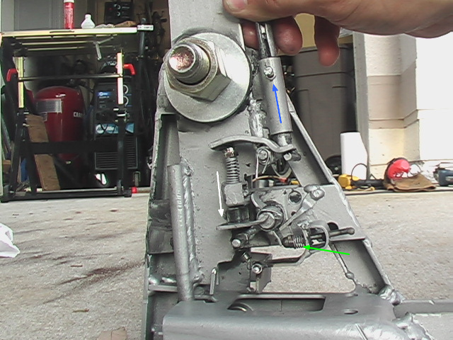
The blue arrow shows where I need to build something to hold the right shift cable in place. The left shift cable, toward the top of the picture can be held in with the usual clip that comes with the car. The Solara cable on the right is built a little bit differently, so I made a little piece that bolts on to hold it in place.
February 1, 2014
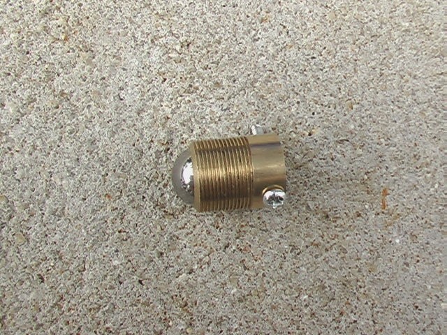
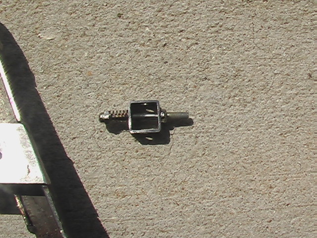
To put the transmission into first, the left lever has to be pulled backward, this equates to a left movement of a single lever, then the right lever is placed where a single shift lever would always go, forward. The right lever stays in place, just like a normal shifter would. However, the left and right movement of a shift lever springs back to center. So to go into 1st, the left lever not only has to be pulled backward, but pressure must be kept on it, until the right lever is moved forward. This makes it a bit difficult. So I bought this little device at Home Depot. It's used to hold screen doors in place, but it will work perfectly for what I want to do.
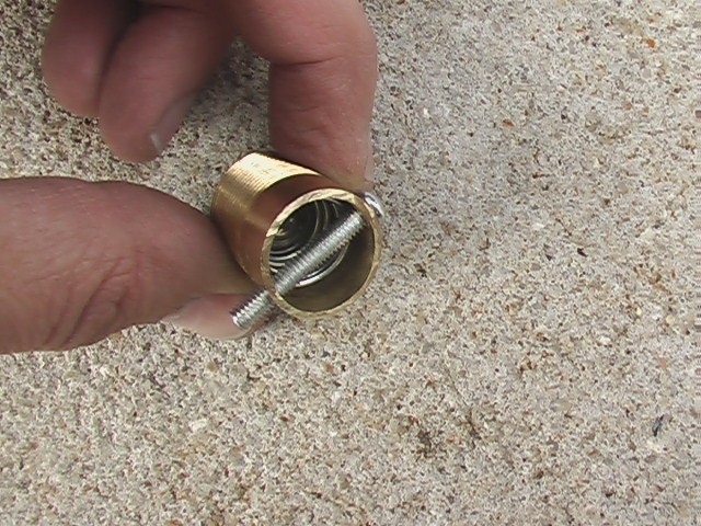
Inside you can see there is a spring which keeps pressure on the ball. It was a little long and interfering with the right side cable, so I cut it down a little bit and drove a screw through it to hold the spring in place. I didn't want any plastic that would deteriorate over time.
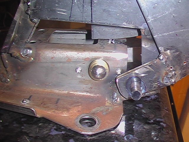
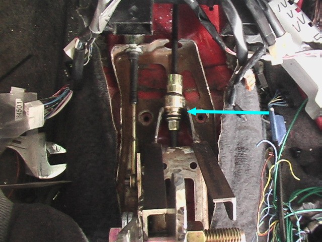
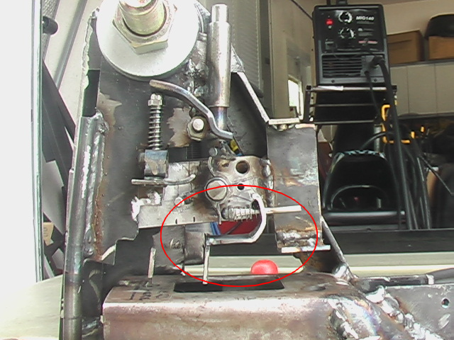
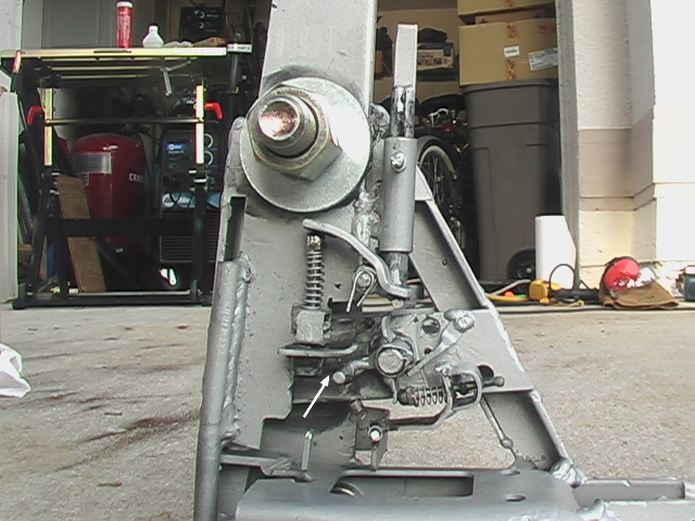
And here's where it's located.
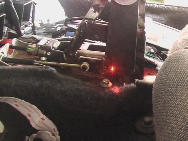
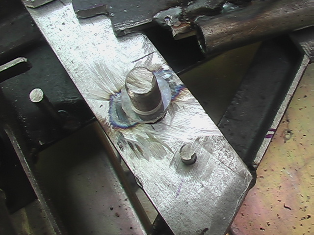
Once the ball was in place, I felt it was crucial to make the detents in the right place, but I wasn't sure how to do it, because the ball was in the way for me to mark it. Finally I came up with the idea to put a laser right on the center of the ball, and then move the lever to the three positions needed and mark the spot, then drill all the way through the lever. It wasn't as easy as it sounds. The laser reflected off of the shiny ball and got in my eyes. I wore a special pair of red glasses that came with my laser aligned radial saw. I also put my welding helmet on. The problem was that I could look at the laser safely, but I couldn't see my own pen mark. Anyway, eventually I got it done and it worked pretty well.
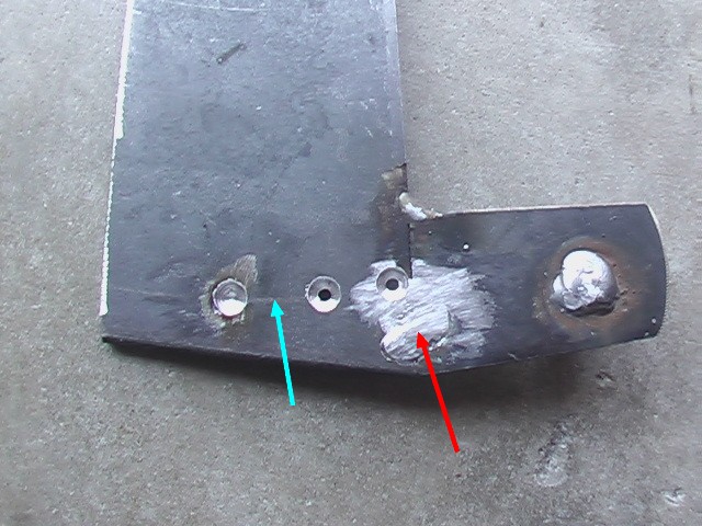
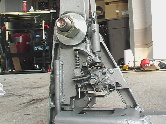
I had played around with the shifter enough that the ball left a mark (blue arrow). This helped me know if I had drilled in the right place. One was off a little bit and i had to weld it back again and repeat. But in the end, it worked out pretty well. The red arrow points to a hole that was already in the shifter. It was so close to where I needed a new one, I had to fill it in too.
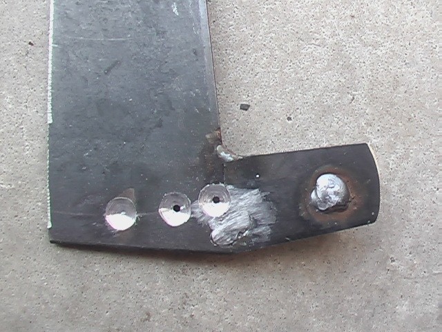
Once I got the locations correct, I used a larger bit to make the detent. The first try didn't hold the shifter in place well enough, so I used a slightly larger bit, until I got the right sized detents. Now the left shift lever snaps into place perfectly. I love it. Notice how the detents aren't evenly spaced. I guess that's just the nature of the transmission.
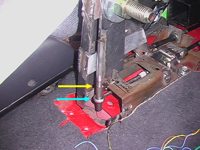
Then I had to connect the right shift lever to the right cable, so I welded this rod onto the lever. It's bent just a little bit at the yellow arrow so that it's vertical when in the neutral position. I thought this would put the least amount of stress on the cable, which has a plastic insert. The blue arrow is where the ring on the cable sits when it's slid onto the rod.
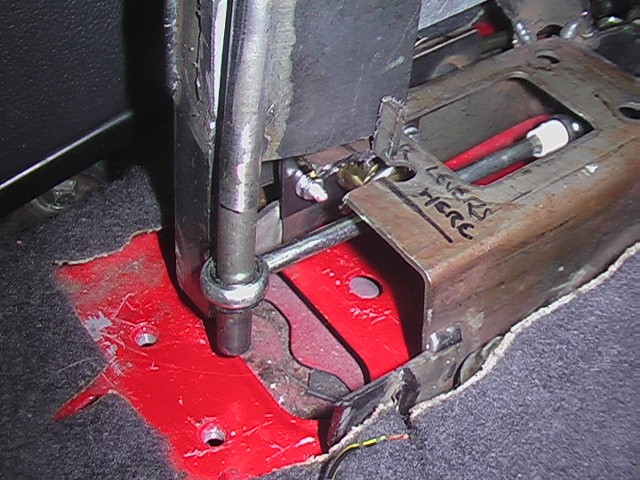
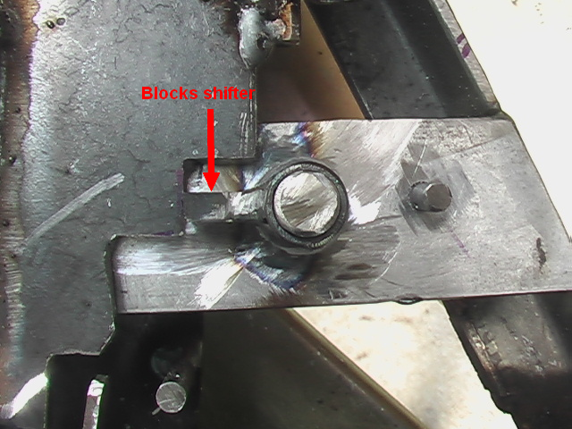
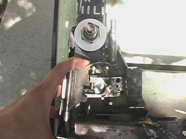
This is where the lever sits in 1st, 3rd and 5th.
This is where the lever sits in 2nd, 4th and reverse.
Because the shifter could be confusing, I want to put a reverse lockout to keep it from being put into reverse while moving. The transmission more or less prevents this, but I'm not sure if it could be forced. The shift throws are short and therefore require a lot of force, I'm concerned that it might be possible to jack it up if I tried to downshift to 4th gear at highway speeds a bit too violently and accidentally got reverse. I'm still trying to figure that part out.
February 7, 2014
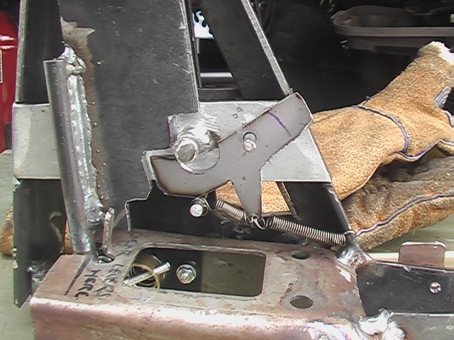
To continue with the awesome twin shift lever mechanism, I worked on the reverse lockout contraption. After about 4 hours of deliberation, just staring at the thing, trying to come up with ideas, I finally decided on this one.
It consists of an arm on a pivot with two springs. The forward spring (on the right) keeps the arm down and out of the way during normal operation. The back spring (to the left) is attached to a pin I welded to the left shift lever (behind the one in the picture). This is the position when the left shift lever is all the way backward. There is practically slack in the left spring and the right spring is pulling the arm into the disengage position.
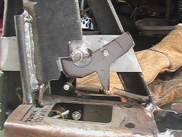
When the left shift lever moves forward to the neutral position(and the bottom therefore moves backward), the pin puts tension on the rear spring and the two springs pull the arm up a little but it is still in the disengage position.
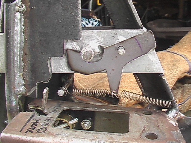
Finally when the left shift lever is pushed all the way forward, the tension in the back spring wins the battle and causes the arm to lift into the engaged position, locking out the right shift lever from the reverse position only.
It works great, but I do have concerns about longevity. The springs could wear out. They're also not very strong, so if the lockout arm gets gummed up or something, perhaps they wouldn't have enough gusto to cause it to move.
Fortunately, I don't think this lockout is necessary, so if it fails it shouldn't be any big deal because the release mechanism that allows me to put he car in reverse, will operate so that if the right gear lever ever gets locked out of first or third gear, I can always pull on the lever that allows reverse to operate and first and third will work again. It's a good failsafe.
I still have to secure the lockout arm and springs, but I'm going to wait until I'm finished because I am still making changes.
Because I figured this would work, I moved on to the release mechanism. The plate in the forground will be a third shift lever. Well not really because it won't move back and forth. It will be shorter than the others and feature a little lever that is lifted in order to get reverse.
February 16, 2014
That idea didn't work! I forgot a stationary third shift lever wouldn't work because it would need to move with the right gear shift lever, otherwise I would have to pull up on the third lever, then move the right one until it was safe to let go of the third one. Very cumbersome and probably a two hand ordeal.
I knew I wanted to use an arm that would slide upward, so I welded a tube to the right shift lever. This is way beefier than it needs to be, but this is the only size of tube I have that has a rod that slides perfectly inside of it. Plus this will keep the part sliding straight and not move around.
So I re-thought the whole idea and came up with a way to keep the same design. You can see that I put a rod that slides perfectly inside the tube. I then welded a little arm to the bottom of the slider. This was supposed to catch the pin (red arrow), so that I could lift it up, causing the lockout arm to disengage. But as the right shift lever moved, the straight arm caught on things. It occured to me that I would have to make the little arm have a curvature equal to the radius at that point from the center of rotation. That's why it looks curved in the picture. Of course, now it's nowhere near the pin. I can't believe I didn't take a picture of it, but I added another pin higher up, that the slider could catch. It's right about were the purple marks are on the structure (blue arrow). I'll try to remember to take a picture and add it later.
I needed to buy some springs that were more robust, so I moved along to the brake lever. You can read about that in the brake section.
February 7, 2014
As it turns out all of the work I did on the lockout was thrown away. The combination of having the first lever control the second lever, but only in three out of a possible nine positions and then having a way to override that short circuited fuses in my brain. I had the sneaky suspicion someone would walk up and go, why don't you just put a pin here, or something equally simple and effective. In the absence of this person, I kept fumbling around. The two extension spring idea didn't work because as soon as I tried to take one off, it broke. When I reattached it the spring tension was wrong. When I tried to adjust the spring tension in such a way as to balance the forces, I just couldn't get it right. I went online to find more duralbe beefier springs and it was a nightmare. They were either too weak, too strong, too short or too long. It didn't matter, the bottom line was that nothing seemed to work.
I went back to the drawing board. I wanted to use the springs in a compression arrangement, where I felt they would be both more dependable and more durable. I ditched the little lockout lever and went for one that was mounted on the main pin. Then I proceeded to have failure after failure. Here some random pics of what was going on during that time. I don't think I need to explain every turd I tried.
I finally gave up and decided to use solenoids to move the lockout lever. I figured that would be easier. Simply press a button and shift into reverse. That's when I experienced a whole new round of failures. Here are some pics.
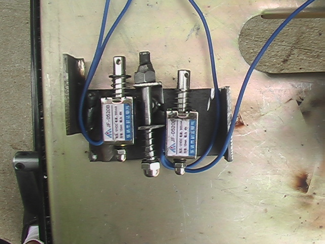
I built this little bracket with two solenoids. In order to keep from drawing current on the solenoid to hold the lockout in place, the spring mechanism in the middle holds it in place so I just have to have an 'engage' solenoid and a 'disengage' solenoid.
Then I built this bracket to hold the solenoids in place. I spent time making it adjustable. It turned out to be a waste of time.
Here they are during installation.
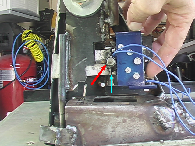
If the bottom solenoid activates, as I'm doing here with my finger, it rotates the wheel (red arrow) by pushing on one of its little ears (blue arrow). This keeps the lever from moving in that direction.
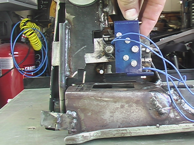
If the top solenoid activates, as I'm doing here with my finger, it rotates the wheel by pushing the other little ear. This allows the lever to move in that direction. Looks great, right? Except there was one little problem. The solenoids were not strong enough to move the lockout lever. The lever isn't hard to move and it will be easier when everything is lubed, but I want something fail safe. If the mechanism doesn't work then I might not be able to shift into 2nd, 4th and reverse. That could make it difficult to drive. Don't you think? You can see a short video of how it DIDN'T work here, if you are interested: Reverse lockout fail.
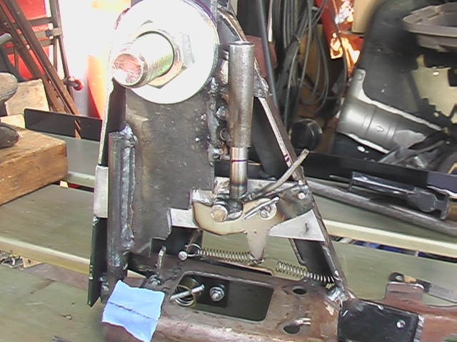
I decided to start again. All of these delays have taken place over the last 3 months or so and have really slowed me down. I do think I have conquered the problem this time. This is the release mechanism to go into reverse.
Pulling up on the shaft (red arrow) causes the rocker arm to rotate, pushing down (blue arrow)on the foot that rotates the lockout lever (yellow arrow).
Because the shaft isn't hooked to anything yet, I've activated it using my finger.
All I needed was a way for the left shift lever to activate the lockout and I'd be done. This involved more failures until I got this to work.
When the left shift lever moves forward this part moves backward and the little plunger rotates the lockout lever into position so that the right lever cannot be moved forward. It only reaches the lockout lever when it is in this position. At all other times it applies no pressure to the lockout lever. If the lever is ever in the way, if the car is brought to a stop in 5th gear for instance, and reverse is needed, then the release mechanism above it is employed. This will be done with a shaft that runs to the right lever. A handle will come off perpendicular to the shift knob and it can be squeezed between the shift knob and the driver's hand. This will all be more apparent when the shift levers are machined and everything is assembled. I believe this mechanism will work. Now all I have to do is, take it apart, clean it up, paint it, lubricate it and put it all together. Then I can finally move on to the handbrake. Which has it's own challenges.
May 13, 2014
Good news! It finally worked. I believe I have everything working. Here is the completed, cleaned-up, sandblasted and painted gear shift lever assembly.
The handles get cut off and pretty machined ones get put on, so I didn't bother painting them. Until I get new ones, I don't want to cut the old ones off.
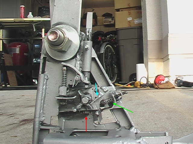
When I lubed everything up, the shift action got smoother, but I think I used the wrong lube (general purpose bearing grease) because it was too thick. The reverse lockout wheel, which was supposed to return to the disengaged position under gravity, wound up sticking in place or moving slowly out of the way. So I wound up putting a little, very weak return spring on it (red arrow).
This is the first gear position. Gear lever one (hidden behind gear lever 2) is backward causing the spring on the far right (green arrow) to move away from the lockout wheel. The return spring holds it against the stop (blue arrow)
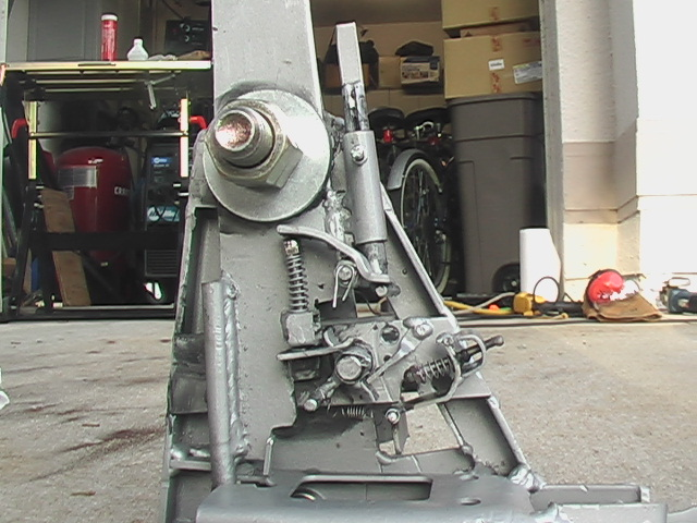
This is second gear. Gear lever 1 is in the same position, while gear lever 2 is pulled backward. It clears all obstructions.
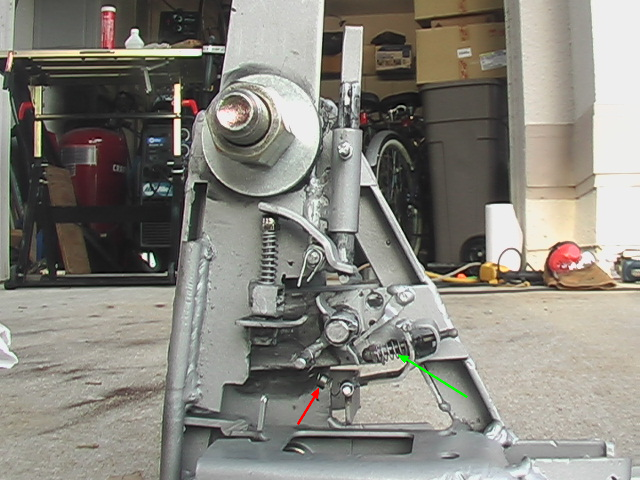
This is third gear. Gear lever 1 is in the middle, while gear lever 2 is forward. The spring on the right (green arrow) has moved closer to engaging the lockout wheel, but does not actually move it. The return spring (red arrow) is loose, but because the wheel is in the disengaged position, there is no need for the spring to be in tension. Gear lever 2 clears all obstructions.
This is fourth gear. Gear lever 1 is in the middle, while gear lever 2 is backward. Nothing else has changed. Gear lever 2 clears all obstructions.
This is fifth gear. This is where the magic starts. Gear lever 1 is in the forward, causing the spring on the right to engage the lockout wheel so that lever 2 cannot be pulled backward into reverse. Gear lever 2 interferes at the white arrow.
Here is what happens if the lever is pushed to reverse, for example accidentally when 4th is being selected. Gear lever 2 interferes at the white arrow.
And finally here is what happens when reverse is needed. The driver pulls up on the lever (blue arrow) which causes the rocker arm to apply pressure to the foot pushing down on the lockout wheel (white arrow). The spring on the right (green arrow) is compressed allowing this to happen. Gear lever 2 can now move backward while lever 1 is forward.
September 6, 2014
I chose the first gear shift lever design of the four above. But before I had parts machined at great cost, I decided to mock them up with a little more precision. I used 1/4" thick balsa wood, cut into the correct shape using a template I printed out. I spray painted them to make them look a little more like metal, but I did not drill the holes in them. I used a permanent marker instead. The way they are designed allows for a number of mounting configurations.
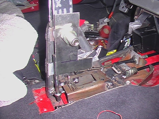
Config 1. I cut off the old shift levers while they were still in the car, that is why the towels are there, to prevent anything catching on fire and all of the metallic dust from getting into things. This is the first configuration I tried. It looked quite different than I had anticipated. I didn't expect it to look like four levers side by side. I expected it to look like two twin levers.
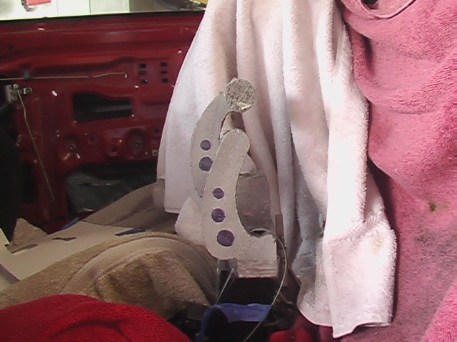
It's hard to tell from this shot, but the curvature of the brake handle and the shifters is a little bit different, which is one of the reasons I don't like this orientation.
Config 2. My wife suggested that if each lever weren't composed of two halves, it might look better. A little duct tape to fill the gap gives you the idea. They look much beefier. Maybe a little too beefy.
Config 3. The brake lever needs to stay the same otherwise it would be awkward to pull. But the shift levers can be spun around facing the other direction. This configuation looked better than I expected, but I just don't like the thicker levers.
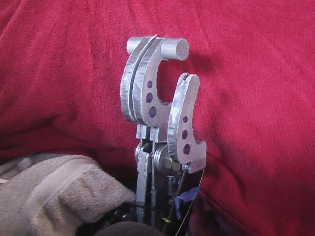
Config 4. Here it is back to the two twin lever configuration. I think this looks better.
Config 5. This is the configuation my wife and I favor. But it was really hard to decide. It was a close call between this one and the next one.
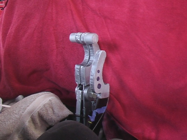
Config 6. This is the configuration some of my friends prefer, I gues because they are all pointing in the same direction. This one was also the most comfortable to place a hand on, but my wife said it made her want to try to push them both forward at the same time. I could be convinced to go with this one. Fortunately, they should be reversible, in case I change my mind.
Config 7. We rejected this one almost immediately. We didn't like the gap between the two shifters. If you have a preference, feel free to email me about it.
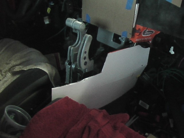
After trying all of those different configuations and photographing them, I used the last little bit of the day to start forming the center console.
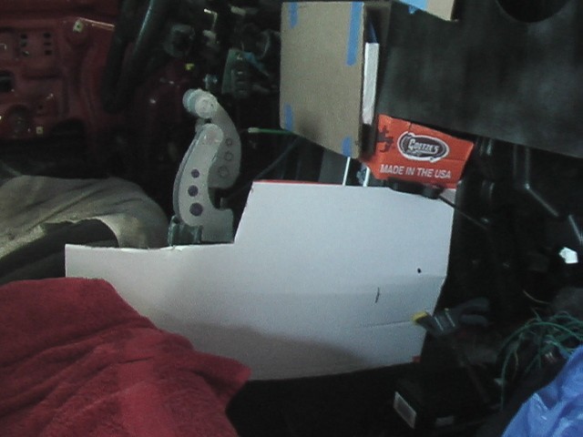
I used an old cardboard box as a template.
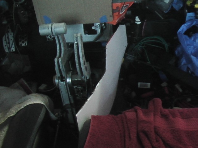
The curves are complex and I doubt my ability to form something like this in metal. I've never used fiberglass, so I have a bit of thinking to do. That was it for the day.