
Electrical
Because I chose to transfer the entire wiring harness from the Solara into the Corolla most of the electrical systems were plug and play. I'd like to say this made the electrical wiring much easier, but truthfully the few systems that had to be adapted from Solara to Corolla were a huge challenge. Running wires through the door panels or along the fender to get to the engine compartment is always difficult. Plus I decided that the typical store bought connectors weren't good enough. Toyota doesn't use them and now neither do I. I purchased professional grade tools to create my own OEM quality connections. This was very, very expensive. I'm pretty sure I spent around $800 on two crimp tools and all of the connector bodies and pins. The results are that I have much higher confidence in my electrical connections.
Here's what they look like.
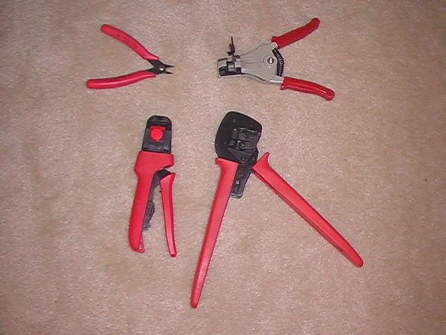
Upper left is a decent wire cutter. Upper right is a decent wire stripper. On the bottom are professional grade crimpers for small and larger wires, from 22awg to about 10 awg. And here's what the crimp looks like:
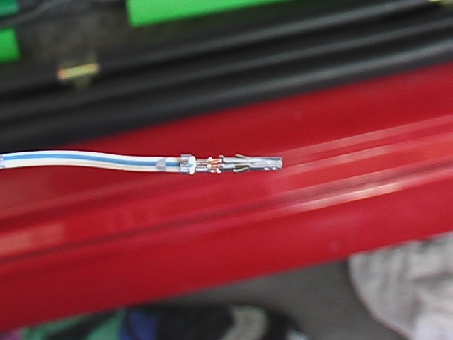
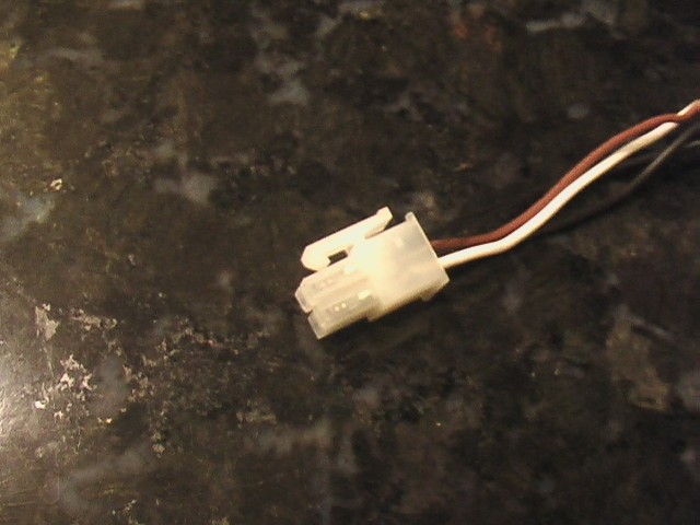
And the final connector:
Headlights
July 8, 2013
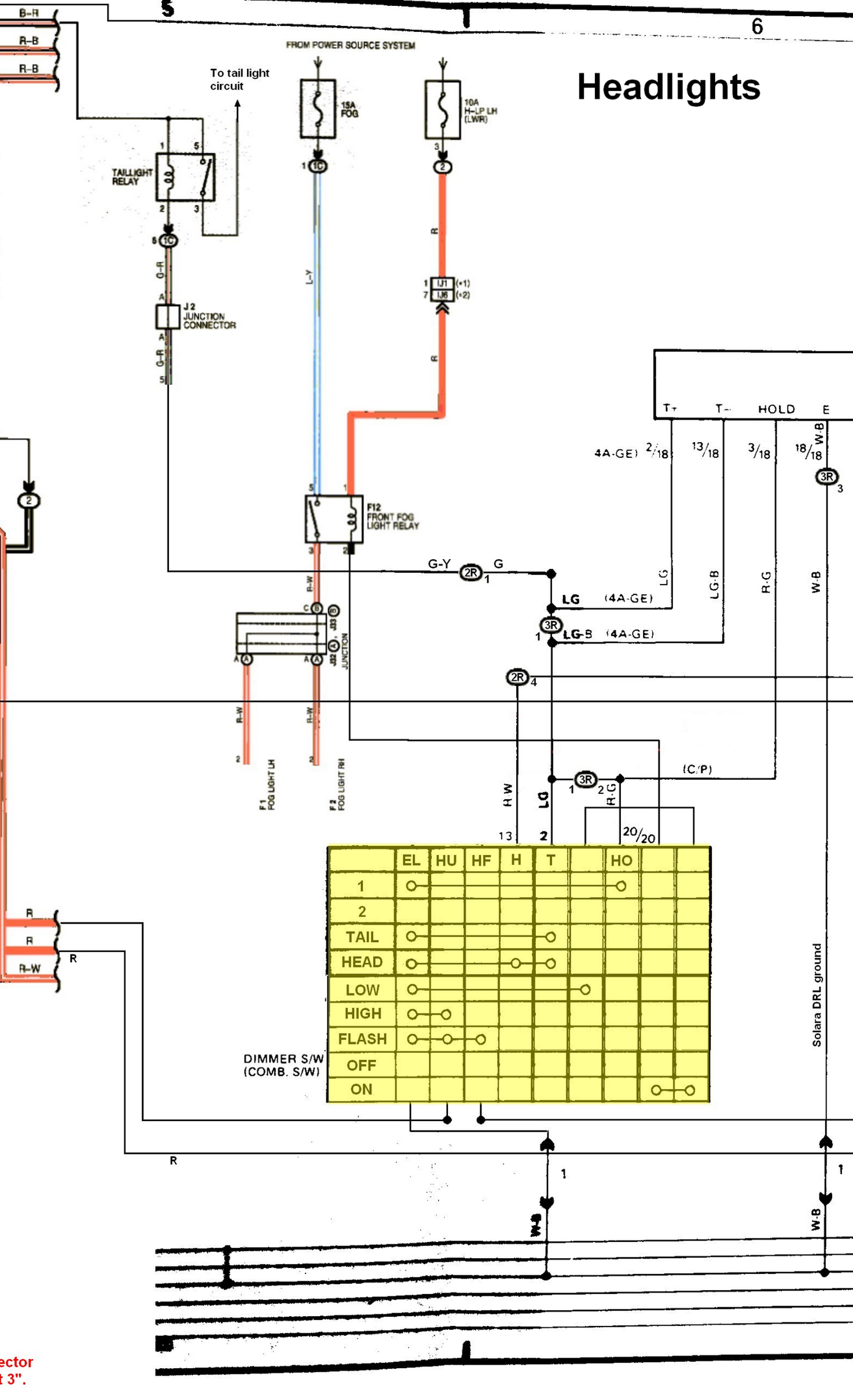
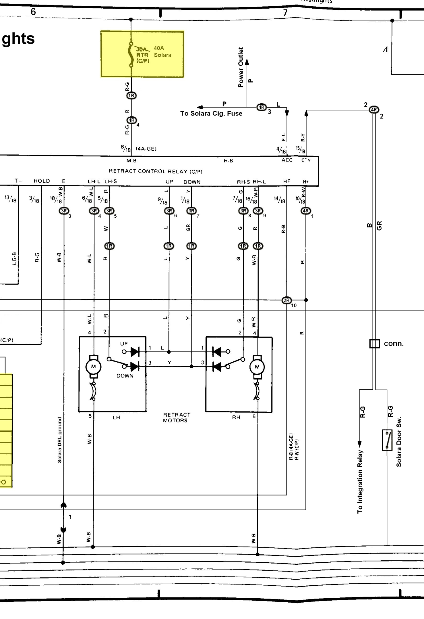
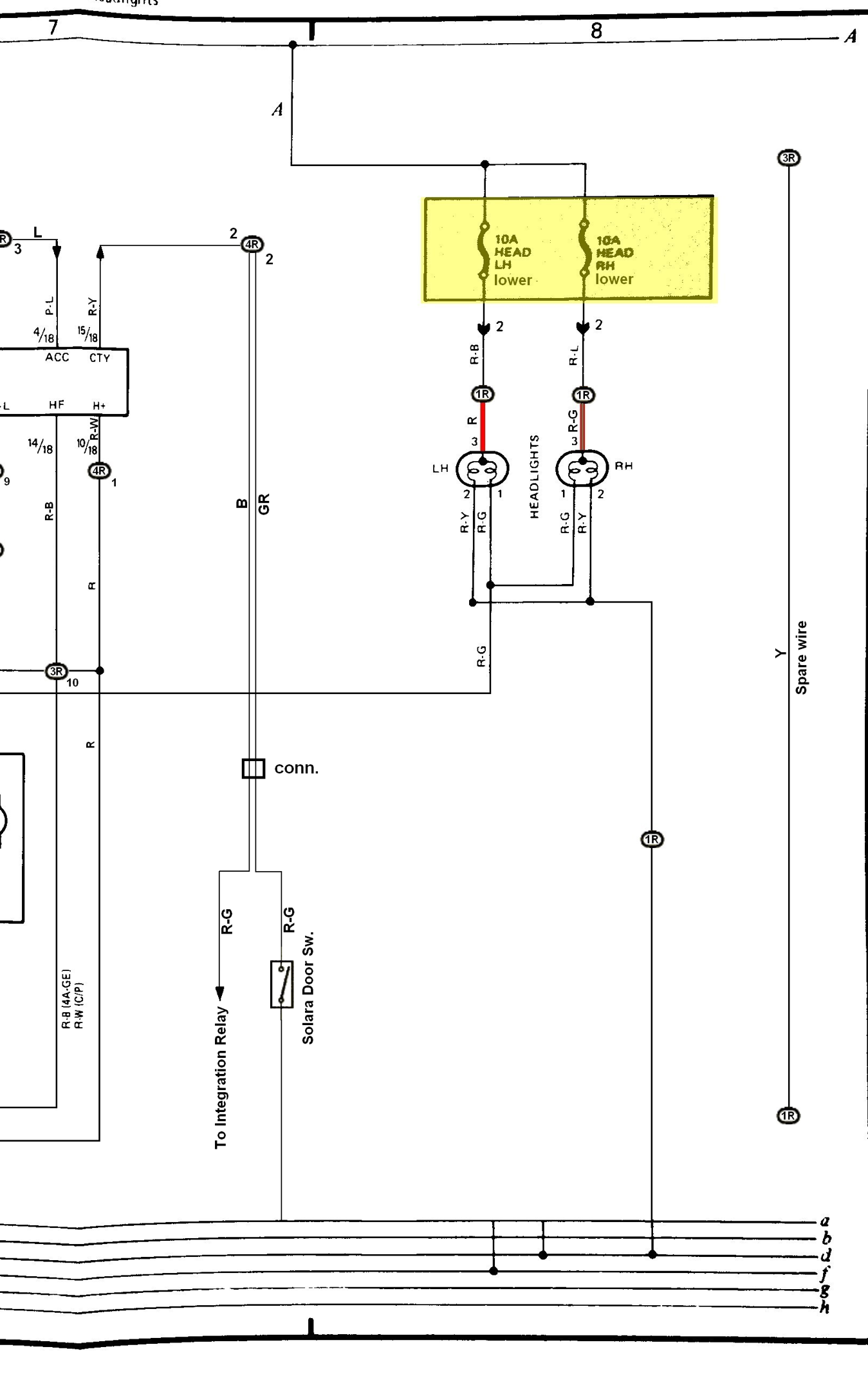
It should be obvious that the headlights would be one of the systems that is not the same on the Corolla and the Solara, since the Corolla has pop-up headlights and the Solara doesn't. So this is the first place I would need to create a hybrid circuit composed of part Solara part Corolla. Because I decided to use the turn signal switches from the Solara, I would have to interface to them. But to keep things working the same with the headlight motors, I decided to use the relay from the Corolla. This meant examining the wiring diagrams from each car and finding the equivalent portion of the Solara schematic relative to the Corolla schematic at the point where the relay joins the circuit.
I created this schematic. Anything in color is original Solara schematic and anything in black and white belongs to the Corolla schematic. I used some of the wiring from the Corolla. I cut my original uncut harness so that everything would fit properly in the front of the car. The connectors that go to the headlights and the wires with the appropriate clips all fit in perfectly. I guess that's just the way it goes when you do this kind of work. No fear!

I realize you can't read that so I'll blow it up section by section. It is important to note that in the bottom left corner, I have listed the connectors I have created to make this work. I put an 'R' next to them to indicate my name.
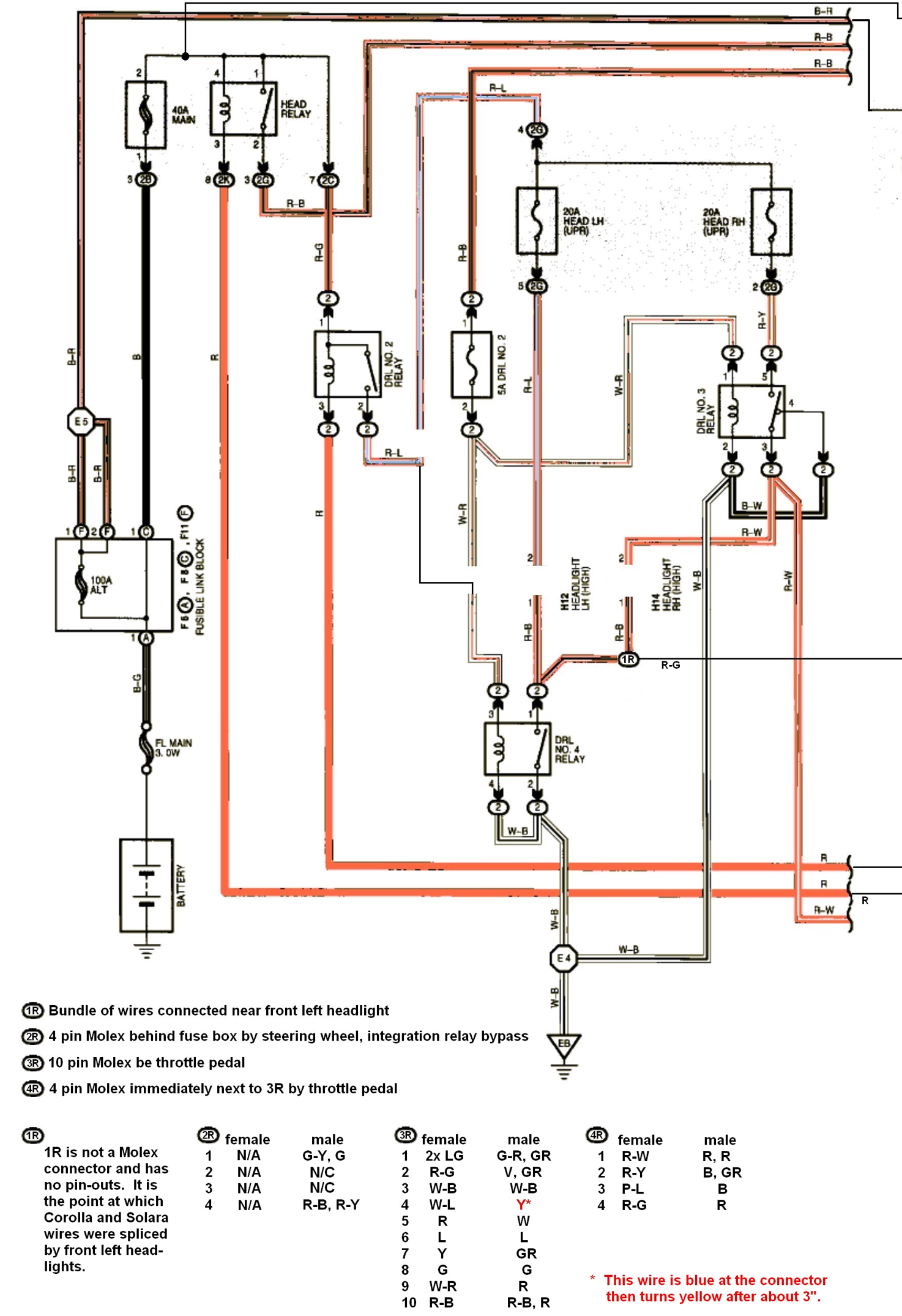
You might notice some portions of the circuit don't seem to connect. That's because those portions aren't used. . . or . . . um, I might have forgotten to update the schematic. I'm going to have to look at that again.
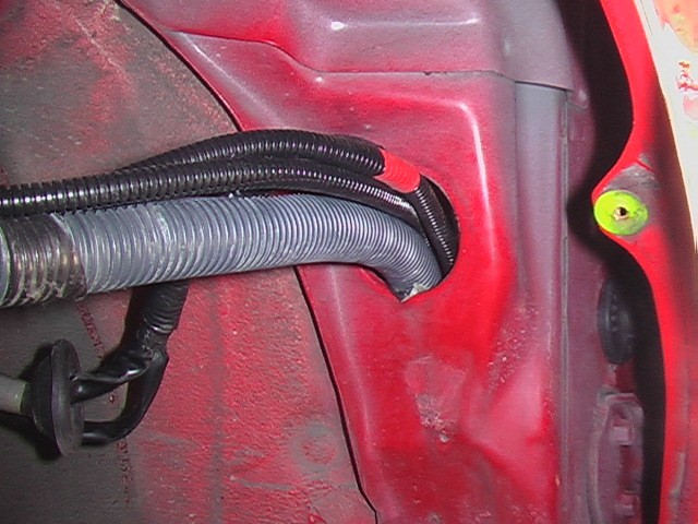
Running the wires was a real pain. You can see I added two extra wire bundles to the existing wires running from the cabin to the front of the car, through the wheel well.
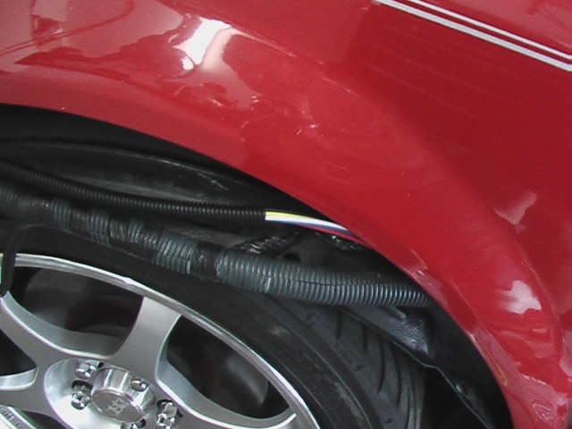
Here they are.
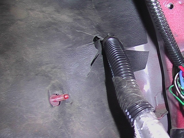
Here's where that bundle comes out. It's near the headlight on the left side of the car.
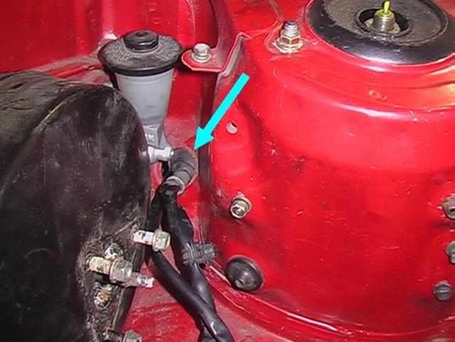
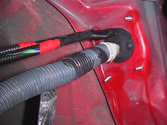
One little bundle comes out next to the clutch master cylinder.
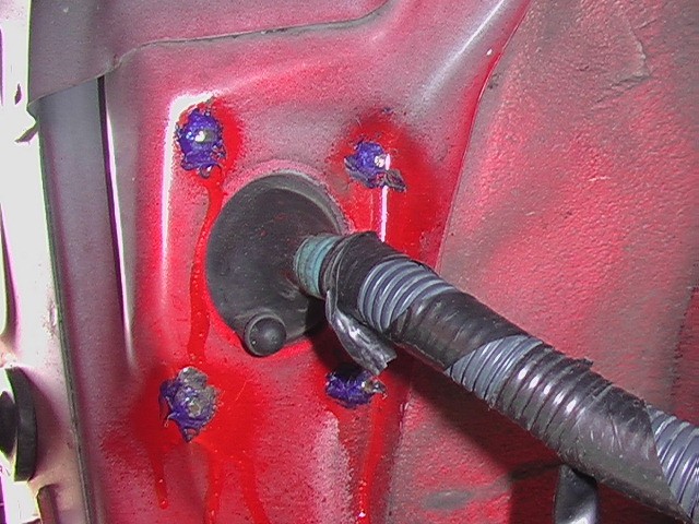
You can't tell, but this Solara rubber gasket booty thing does not fit in the Corolla hole. I could have opened up the hole but that would have left a sharp edge. The stock holes have a little lip on them that softens the transition and helps fill in the groove on the rubber boot for a better seal.
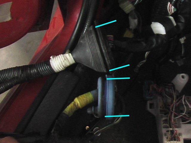
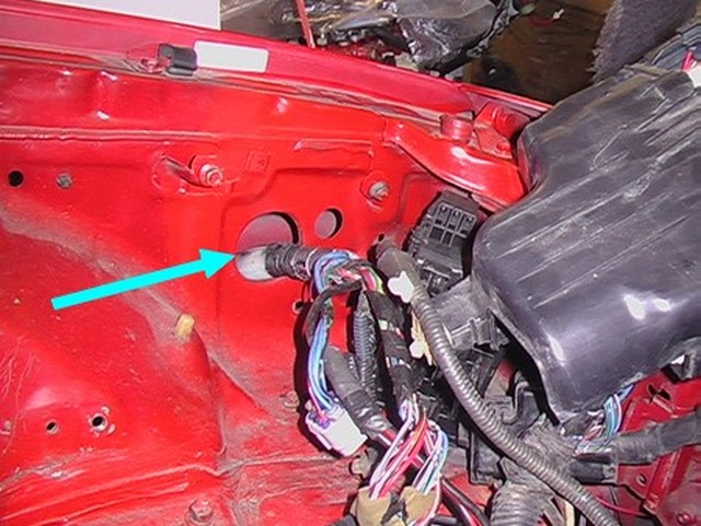
Because the wiring bundle for the Solara was so much thicker than that for the Corolla, the rubber gasket that goes through the firewall toward the engine was also bigger in diameter and would not fit in the hole. The blue one is for the Corolla.
I thought about trying to put the Corolla gasket onto the Solara bundle, because the wire bundle is not physically larger than the gasket, however the connectors on the end were. The prospect of trying to get the boot off of the Corolla wiring bundle and onto the Solara bundle was just too daunting.
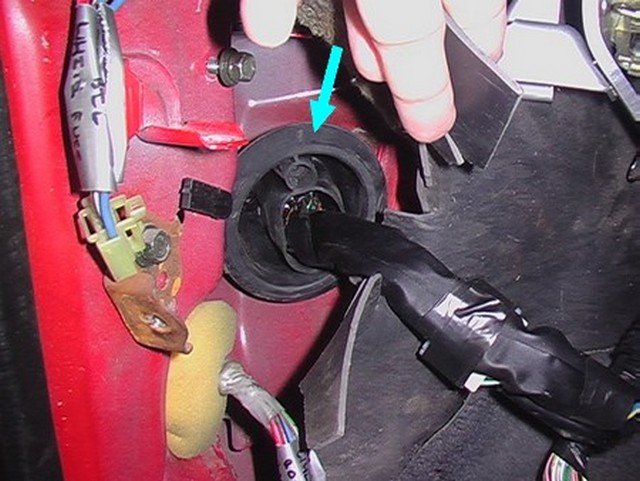
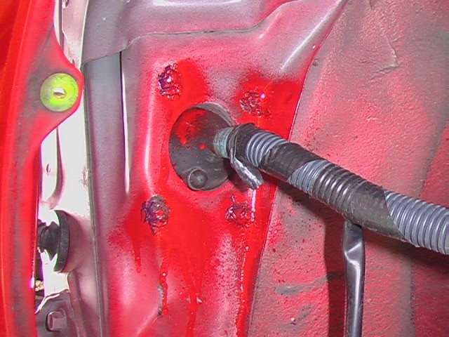
This is inside the car on the driver's side.
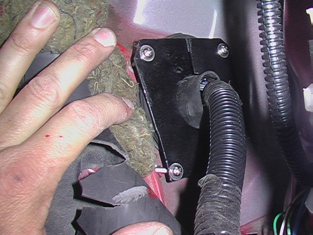
I needed a way to keep water from entering the car through this area, so I came up with a way to press the Solara rubber boot up against the Corolla hole. If I forced the rubber boot into the Corolla hole, it would have puckered and leaked. So I took a plate, and bolted it to the car sandwiching the boot between the plate and the car and evenly distributing the rubber boot in the hole for what will hopefully be a weather-tight seal.
Here's what it looked like on the other side. This is in the wheel well, underneath the plastic liner. You can see I drilled four holes to bolt the plate to the car. You can see some paint drips already there. After I drilled the holes I wanted to make sure to get some paint on the bare metal in the holes.
I did the same thing on the passenger side. To keep those bolts from rusting or leaking, I coated them in RTV silicon.
Then I gave them a shot of paint, just in case. You can see that the bubber boot is squished into the hole pretty tightly. I'm sure this is a good seal.
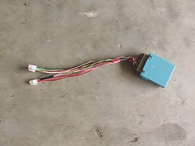
This is the headlight relay from the Corolla. As you can see I have connectorized it to make it ready to integrate into the Solara wiring. If I've done my job right, the headlights should pop up and function exactly as they did before, but using the Solara controls on the turn signal stalk.
It looks like the connectors could be confused, but in actuality, the pins inside the connectors are reversed so they only plug in one way.
Power Windows
August 31, 2013
My Corolla came with an auto-down feature on the driver's side window. I've always thought that was the coolest thing. What I didn't understand was why only on the driver's side. And why not an auto-up? I guess they didn't want kids heads getting caught in there. Either way, I'm an adult with no kids and not overly concerned about stupid people getting their body parts caught in my windows. So I decided that I would finally make my car's windows do exactly what I want them to do. In fact, I've gone one step further. I'm including the power sunroof in the scheme. The original Corolla also had a sort of safety stop on the sunroof, so not only did you have to press the button and hold it, but you had to let up on the button and press it again after the safety stop.
Well, not anymore. I was going to design my own system, but after some research on the ol' interwebs, I found a part ready made to do just the trick. It's actually made for car alarms, but I was able to easily adapt it to my purposes. I should say as of April 18, 2014, that I have yet to test them and I have no idea how durable this solution will be, but the product is a 530T Window Automation System from our good friends at DEI. You can find directions for install here: http://www.directed.com/guides/manuals/ig/accessories/N530T_1-00.pdf. I think they are discontinued now, but I also think they sell a similar product. If it works properly and it better because installing it was a real PITA, then I will be able to open or close the driver's window or the passenger's window from a single press of the button on either side of the car. I will be able to open or close the sunroof with a single press of the sunroof button AND I rigged it so all of them will open or close with the single press of a button. Can't wait to try it out. Here's the schematic for that:
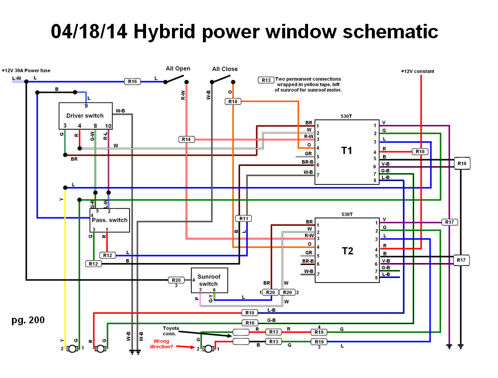
It looks pretty crowded, but essentially the lines between the switches and the motors are cut and the 530T devices are inserted.
Gauges
October 31, 2015
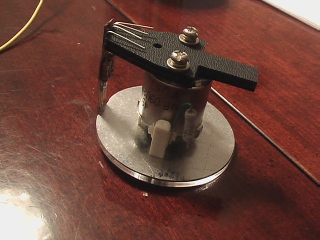
The gauges could be considered Interior or they could be considered Electrical, but because I had to wire them, I consider them electrical. I'm using the guts of the gauges from the Solara and creating my own look inside of an aluminum housing. To do that I first had to understand the Solara gauges. I did some investigating in the schematics and traced the wires down to connections on the back of the cluster. Here's a pic.
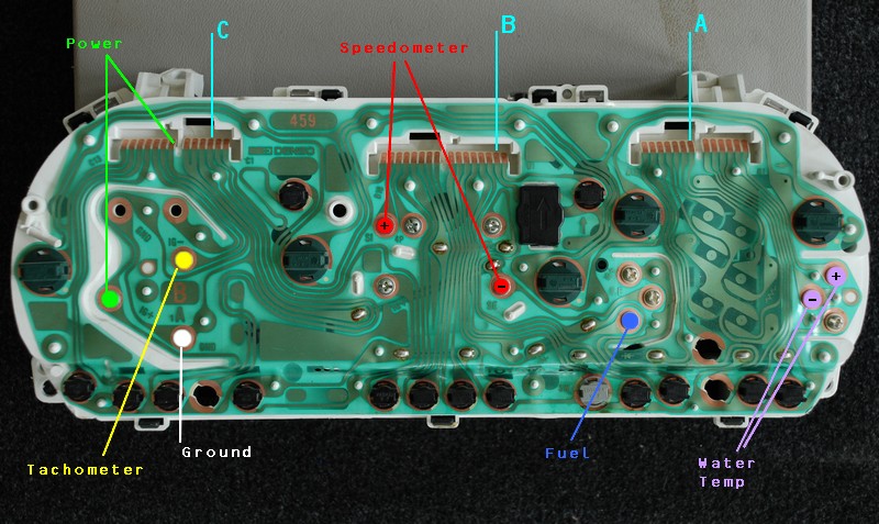
I pulled out the schematic and figured out how to connect the speedometer and tachometer.
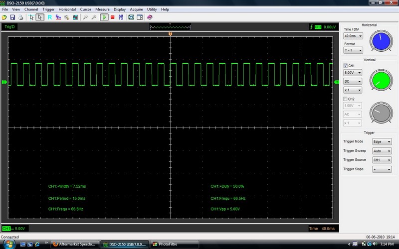
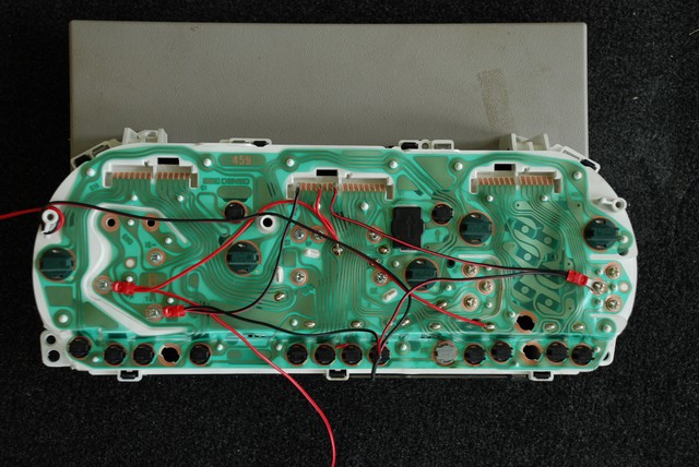
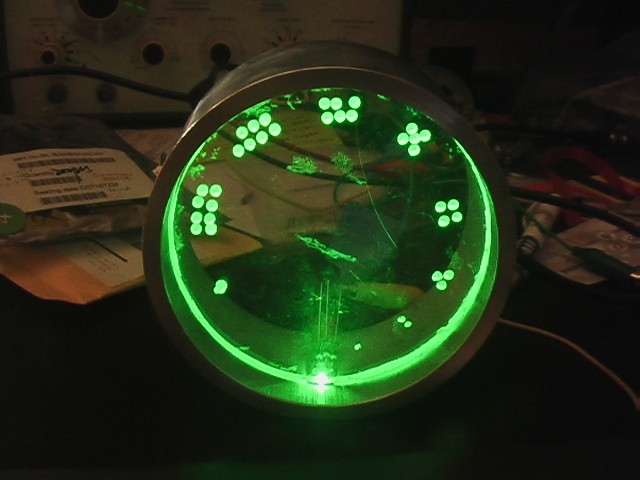
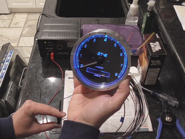
Once I did, I had to figure out what kind of signals made it work, so I connected my oscilloscope to a function generator and started feeding in pulses. I may have looked it up first, I don't recall. Either way I started at 5V and worked my way up, changing the pulse frequency. In the end, this is what wound up making it run at 60 mph. If you can't read that it's: 66.5 Hz, 5 Vpp, 50% duty cycle with about a 12V DC offset. NOTE(02/26/17) After checking this out with a spare gauge at home, I believe the actual pulses that drive this are 12 Vp, 50% duty cycle and roughly 1 Hz per mph, so 66.5 Hz for the picture. I was able to get it to work with pulses as low as 3.9V. It was my plan to actually have two odometers. One to track the miles on the chassis and one to track the miles on the engine. I just wasn't sure if the speed sensor could drive two speedometers. I think I will give it a try
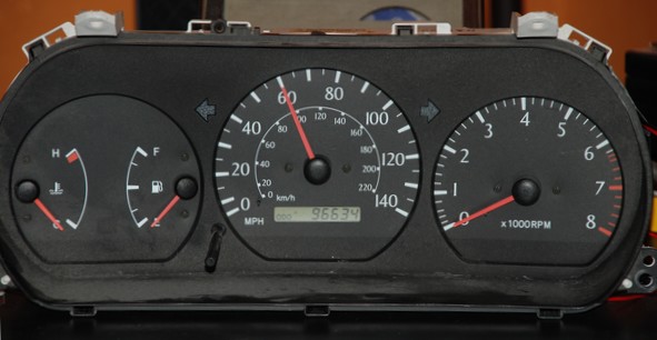
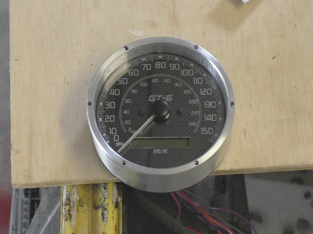
And there it is going 60 mph on my desk! I ran this up to about 120 mph and left it for a while until I got the milage to match what is on my Corolla, 174,315
February 26, 2017
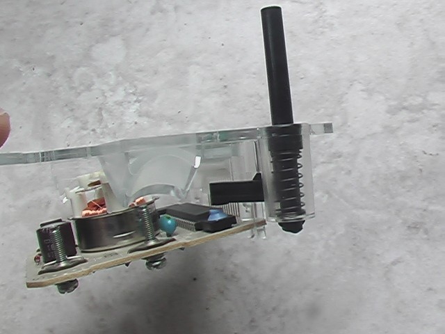
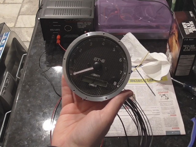
I disassembled the gauge so that I could make my own from the parts.
I wanted the machined aluminum look, so I purchased some 4.5 inch aluminum tube with a 1/4" thick wall. The inside diameter of the tube was big enough to accommodate the sweep from the needle of the Solara speedometer. To complete the gauge it will need some machining, but I like where this is going.
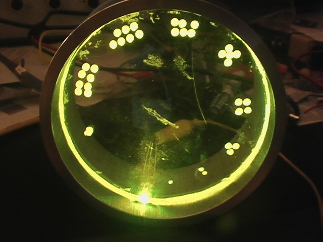
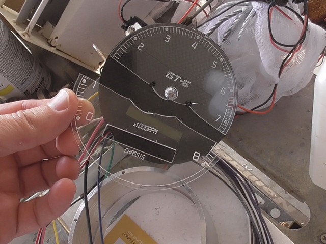
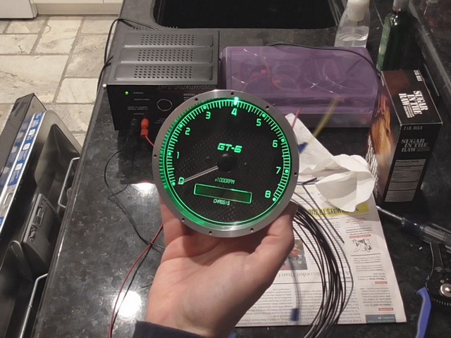
Below is the concept for how the gauge will look. I've always loved the look of edge lit items and so I decided to do my gauges that way. In order to fit an LED inside the gauge it needed to be small, but I wasn't sure a small one would illuminate the whole gauge. So I roughly cut an old piece of plastic I had in the garage. Then in order to see how deep the numbers of the gauge would have to be, I drilled a series of holes to different depths around the dial so I could see how well they would illuminate. Going anti-clockwise around the dial, the single dot is not very deep at all. The two dots are a little bit deeper all the way around to the big single dot on the other end, which goes nearly all the way through the material. As you can see not only does the little tiny 1206 surface mount LED have enough gusto to illuminate the gauge, but nearly any depth etch into the plastic will be visible. That also means that any scratches will also show, so it is important not to scratch the face when working with the material. As you can see from the pictures below, because I used an RBG LED, I can dial in any color I want.
Somewhere on the web I found an excellent paper on edge lighting. There were a lot of tips for making it work well, but I have to say, the edge of this plastic isn't even polished. It's very rough and it still works fine. Nevertheless, there are still some suggestions. Apparently it looks better if it is etched on the backside. So reversing the image is recommended. Also, acrylic should be used, because it will not turn yellow in the sun. Don't use polycarbonate.
I used 1206 surface mount LEDs to make this. Unless you have a lab with a microscope, a really good soldering iron with a fine point tip or some other professional equipment, I do not recommend going any smaller than this. They are very difficult to work with and it took me all day to make six of these, using a primitive magnifying glass. If you grab them wrong with your tweezers they will jump away from you like a flea. Also, get a bunch of extras. The first one I mounted, I got a little crooked and the only LED that would light up was the red one. Removing it without destroying it is virtually impossible. It's better to to just put a blob of solder over the whole thing and remove it destructively all in one swoop. I think I wasted about six of them, giving me a win rate of about 50%. Naturally, a larger LED will be easier to work with, but then you have to have enough room along the edge of your plastic to handle the larger LED. When I tried to run little wires to the LEDs the pads on the LED ripped off with the slightest movement. So I made a little PCB with some very thin 0.005" copper clad PC board material and an exacto blade. Here's what they looked like.
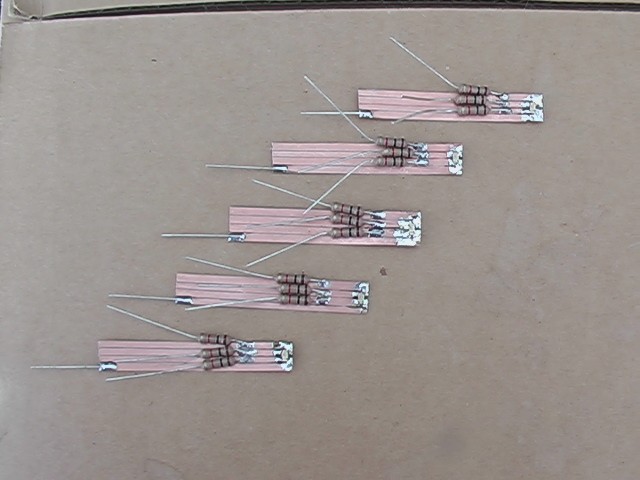
I got the material from the scrap bin at work, but you can find thin PC board (aka laminate, circuit board, printed wiring board, etc.) on ebay.
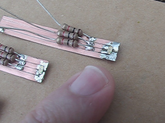
Here's my pinky finger to give you some scale. The LEDs are hard to even see. This board is not real pretty, but no one will ever see this part.
There are a couple of issues regarding the LED lighting. In this configuration, if the voltage goes down enough, the LED just shuts off. In fact, these LEDs call for about 560 ohms of resistance and I have used a 1 Kohm resistor instead because it still lights and this will protect them should the voltage go to say 15 V. This means that I will not be able to dim my gauge lights. A microprocessor can do it, but I'm just not sure it's worth the effort.
The other issue is that with the lights out, it may be hard to read the gauge. An option is to simply leave the gauge lights on all of the time. I'm ok with that if necessary. I'll just have to see what it looks like and make some of these decisions after the car is running. More later.
March 4, 2017
Something fun I get to do is, design the way the gauge looks. Since I will have the plastic laser etched, I will need to provide them with a file to use. To do that I have to figure out where to put the tick marks on the circumference to show what speed I'm going. At this point, I should mention that the way guages are designed, they can never truly be accurate. In the case of the Solara, the speed sensor, which is mounted on the transmission, outputs 4 pulses for every revolution. I presume this is the output shaft, so essentially wheel revolutions, otherwise it would change with which gear is selected. So if the tire diameter changes, so do the number of revolutions. Because tire manufacturers don't have the exact same diameter for the same size tire, it would change if a new tire brand were chosen, not to mention the fact that the tire wears, so over time the tire gets a little bit smaller. My job is to get as close as I can so that I don't get speeding tickets.
Since I know the Corolla tires are smaller than the ones that came with the Solara, I know I will have to change the spacing of the tick marks. But how much? This has turned out to be a bit of a problem. The manual states that the speed sensor outputs 4 pulses per revolution, but I had to input 66.5 Hz to get the speedometer to show 60mph. That equates to a tire diameter of 20.17". This doesn't make sense to me because the tires on my Corolla are about 23.1" in diameter and the original tires should have been about 25.7" in diameter. So 66.5Hz indicates a wheel smaller than either of these. And worse than that, the amount it is off is not evenly one half or one quarter, which would be easy to understand. it's 78.5% off from what it should be. When the car is running, I could check the speed with GPS and the good news is, if I got it wrong and had to change it, the plastic pieces that I would have to have re-done are inexpensive. Unfortunately, I think it would be a pain to change it. Either way, I would like to take a shot at it now instead of when the car is running, because I don't want to have a long punch list of items that have to be done again after I finish. I'm anxious to drive it. So, the bottom line is, I'm going to trust the oscilloscope and use the measurements I made to create a design.
I pulled out the schematic and figured out how to connect the speedometer and tachometer.
April 29, 2017
The design of the existing speedometer made it much easier to use a slightly different layout than I would have chosen ideally, but it was worth the trade-off. Here is what I have come up with so far.
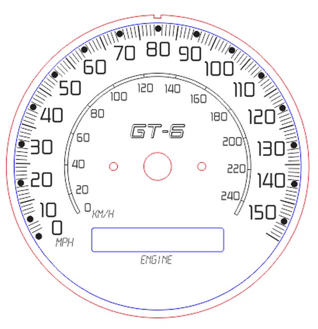
This is what I came up with for the speedometer. If I do things right, the beauty of the design is that I could replace it with something different with relative ease. Well, that's the idea anyway.
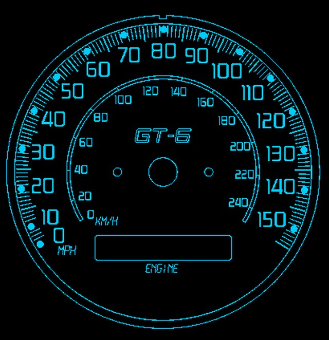
This image is really low rez but it gives you the idea of what it might look like when lit blue.
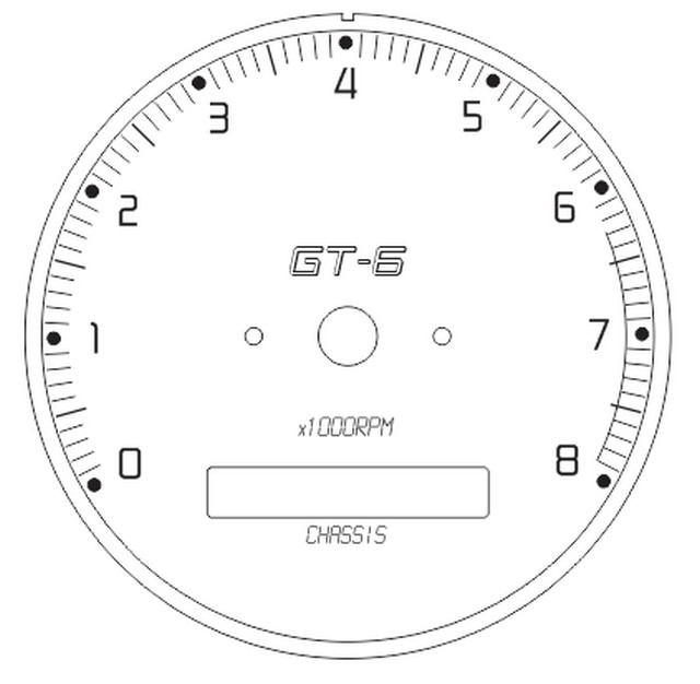
Here's the tachometer.
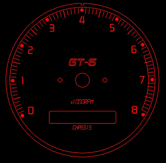
And what the tach might look like if I chose to display it in red.
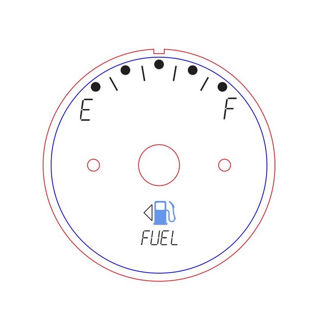
And the fuel gauge.
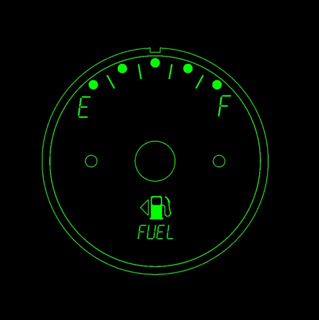
And the fuel gauge if I choose green. The thing about the fuel gauge is that you can see the needle won't sweep much, so it will be even less precise than it was originally. I don't like this but the original design had an arc with a much larger diameter, which wouldn't fit inside the housing. If I moved the center of the needle, which also doesn't quite fit in the housing, downward so that it isn't at the center, I could solve that problem. However, the oil pressure gauge and the boost gauge are not from this car and are of a different design that has the needle at the center. I don't think I can change them, so this is how I plan to do it.
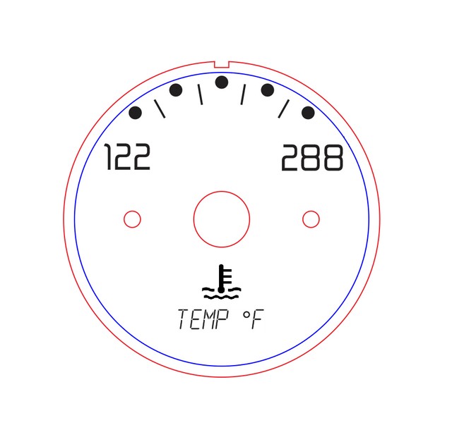
Here's the temperature gauge. It has the same sweep problem as the fuel gauge.
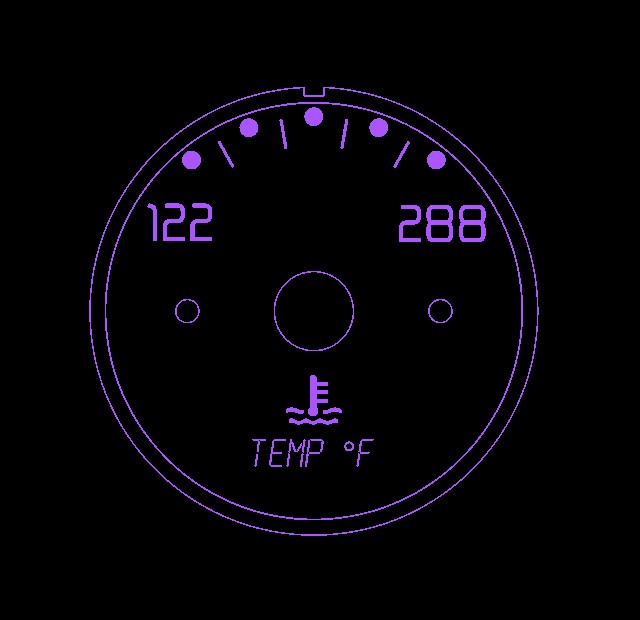
And here it is if I chose purple.
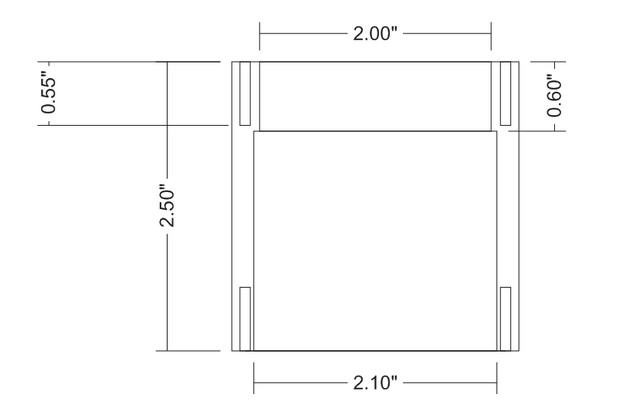
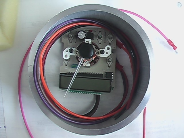
That's as far as I got with the gauge face design. Here is a drawing of what the small housings will look like.
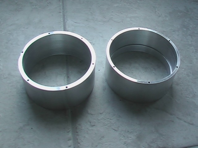
The speedometer and tachometer housings are already done and this is what they look like. The one on the left is viewed from the front and the one on the right is viewed from behind. You can see a little lip machined into the housing. The plastic face will slide in from the back until it hits the lip, which also hides the LED from direct sight.
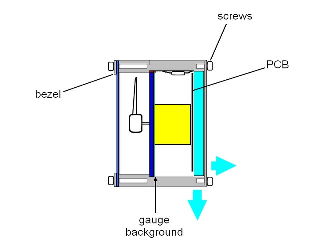
Here's how it's all supposed to go together. The dark blue parts are clear plastic. The yellow part is the gauge motor and it's attached to the PCB in the back. Two screws (not shown) hold the gauge to the plastic. The tiny red part at the top is the LED, which lights the plastic on it's edge. By placing it behind the lip of the housing and putting it on the top where it's out of sight lines, I'm hoping it won't be visible. There are however a couple of problems. I want to slide the stuff on the inside into the housing from the back. The light blue area is all I have for all of the wires. I'd like for the wires to go out of the side, but I want a connector on it and I don't have any connectors that could go through a hole that small. If the wires can't pull out of the housing, they will prevent the gauge from being removed from the housing. So they'll have to go out the back, but that doesn't look as good and might interfere with where the gauge is mounted. Arrrrgh.
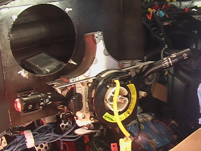
And here's where the gauges will mount. You can see I blew a couple of holes in it at the top, but that won't matter. It will be hidden by something decorative. In this position, the speedometer and tachometer will be visible through the steering wheel and will tilt with the steering wheel. The guages will have to be very shallow and this may mean a lot of glare from the sun. We'll just have to see.
October 17, 2018
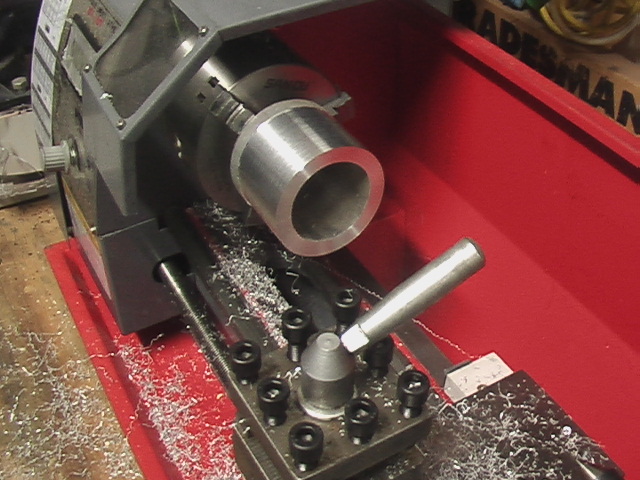
I attempted to make the bezels for the small gauges on my new CNC router, but aluminum is difficult for the machine and the result wasn't good. I think a good result can be had with practice adjusting the settings. At least I hope so because I plan on doing the far more complicated gear shift levers on the maching soon.
To the left you can see I did them on a mini-lathe I ordered from ebay. This was the first part I did on the lathe and I was very careful, taking very small cuts and listening for chatter. Things were going very well, but during the first part the motor started slowing down, jerking and making noise. Man, I knew these things were cheap, but I thought I could at least get through one friggin' part.
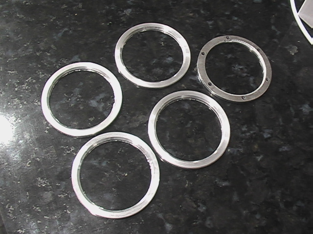
Here you can see the difference in quality between the parts done on the lathe and those done on the router. The face of the router part (on the right) was not polished so it shouldn't look good, but look at the quality of the bevel on the inside of the routered part versus those done on the lathe. Also the part on the right is not round. It came out a little bit oval. The outside finish isn't very good either.
The rough edge on the inside of the parts done on the lathe, still needs to be removed. That will be perfect when I'm done.
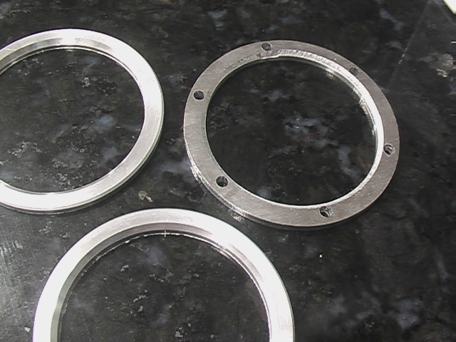
Here is a closer picture. Obviously the holes still need to be added.
November 17, 2023
In the time since I last posted, I have completed all of the guages. Let me show you some stuff along the way.
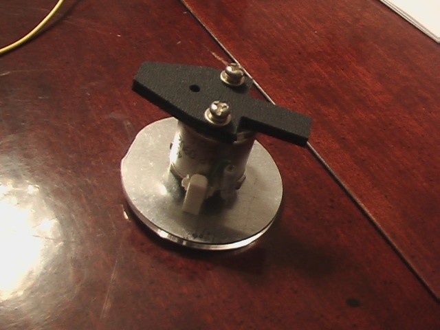
This is the back of the fuel gauge. I made the little black plastic part that serves as a support for the LED board and keeps the guage from falling over inside of the housing. It also, serves to apply pressure that keeps the face of the gauge pressed up against the front of the housing. Adjusting the thickness of this part can shim the part if I use a thicker or thinner background for the gauge.
Here it is with the LED board in place. The plastic keeps it pressed up against the housing. I am concerned about robustness of this design. Again, I'll drive for a while and see if anything fails and burn that bridge when I get to it.
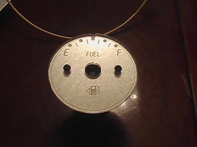
This is what the fuel gauge looks like from the front with an aluminum background. It's all right, but ultimately I decided I didn't like it. The pattern in the aluminum isn't that attractive and if the light changes, the gauge is difficult to read. See the next picture.
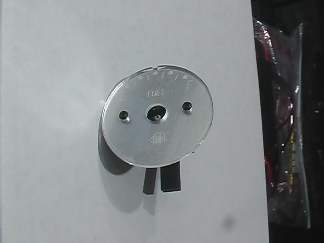
You can see how hard it is to read. Here's a little fun fact, if you didn't know. A little arrow next to the fuel symbol indicates the side of the car where you can find the fuel filler. So if you are ever in a rental car or something and you pull into the gas station and you're not sure which side to pull up on, just look there. I love this.
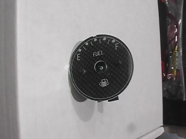
This looks much better. Don't you think? Much easier to read, too.
This is how the speedometer came out. I just love it. It is missing the top cover, where there are bolts holding it on, but I don't have a picture of that and at the moment, there is a protective cover on all of the gauges, so I don't want to disassemble them to take new pictures.
When I was putting the tach together, the drill got away from me and broke it. No problem, I thought. I always get spares, so I went into my office to collect the spare. You can probably see where this is going. Yup, I had spares of every single gauge EXCEPT the tach. Doh! I think what happened was the guy who laser cut them, has a certain size sheet of material and it costs the same to fill it up if you use the whole thing. It probably worked out that there was enough room to everything but that. So I contacted him to make me a new one but for some reason, it didn't work. Either he was too busy, didn't want to do a small job, or the price had gone up so much. I don't recall. Anyway, I decided to just make it on my CNC and lo and behold it actually came out better than the laser cut pieces. Ok, lessen learned. From now on, I'm making them myself.
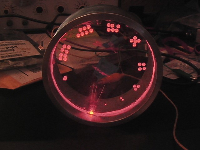
This is how it came out. But I just had to light it up.
It looks so cool. I get excited about driving this thing every time I work on it. I can't believe it's been 13 years since I started. I still have so much to go, too. Ugh.
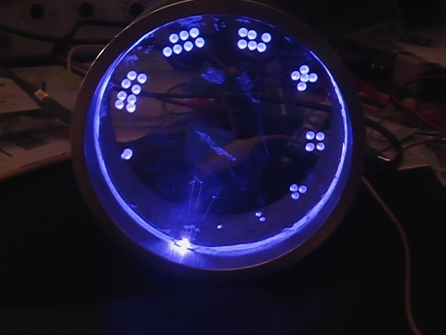
And blue. Nice.
As it turns out, I don't have any pictures of the other completed gauges, but I think you get the idea. I'll try to remember to upload them when I install the gauges in the car and remove the protective covering.
Power Door Locks
August 31, 2013
The beauty of re-use is that sometimes parts from two completely different models will fit. A prime example is the innards from the 2002 Solara door locks. I was able to pull the guts out of the Corolla cylinders and replace them with the solara guts and voila, my whole car is keyed properly. A lot of this is more mechanical than electrical, but the door locks are powered, so I'll get into that. Here are some pics.
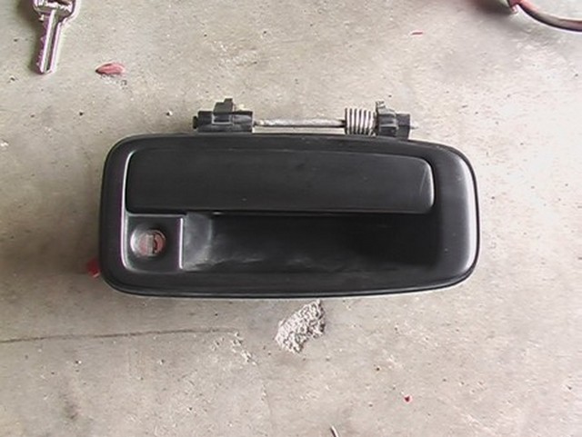
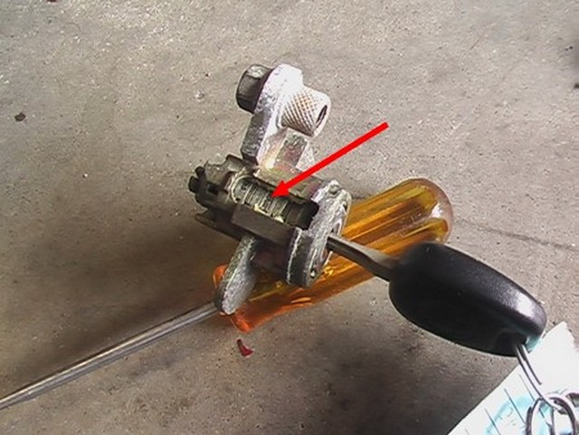
Step one is to remove the door handle, which requires removing the interior door panel to gain access to two screws on the back.
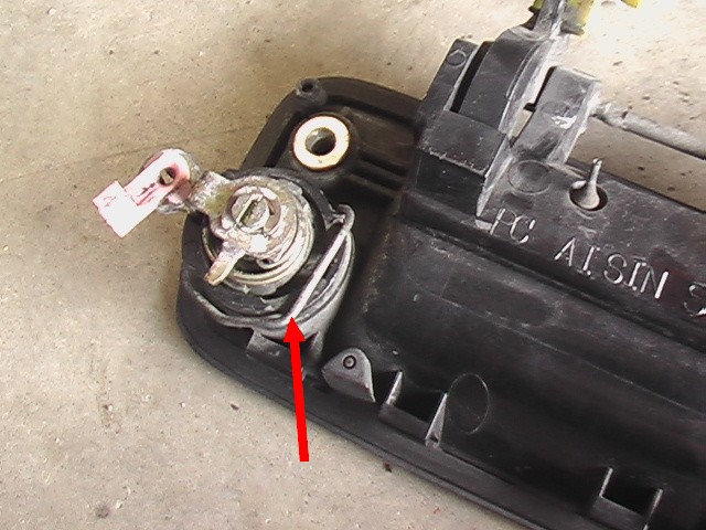
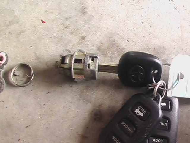
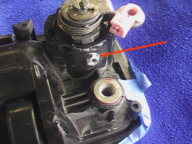
After removing the door handle the lock is super easy to remove. Just pry the little clip (red arrow) out of its little slots and the cylinder comes right out. In this picture, the clip is already partially out.
Here's what it looks like out of the handle. There's a little C-clip on the end of the center post that holds the little arm on. That arm connects to a rod inside the door and allows the door to be unlocked by using the key.
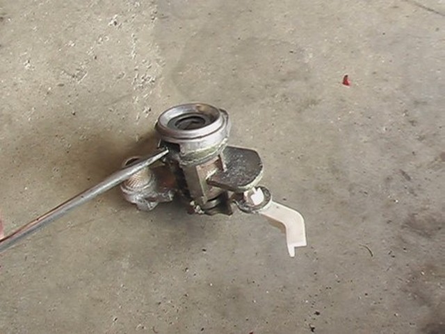
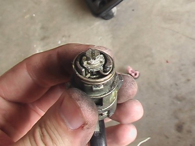
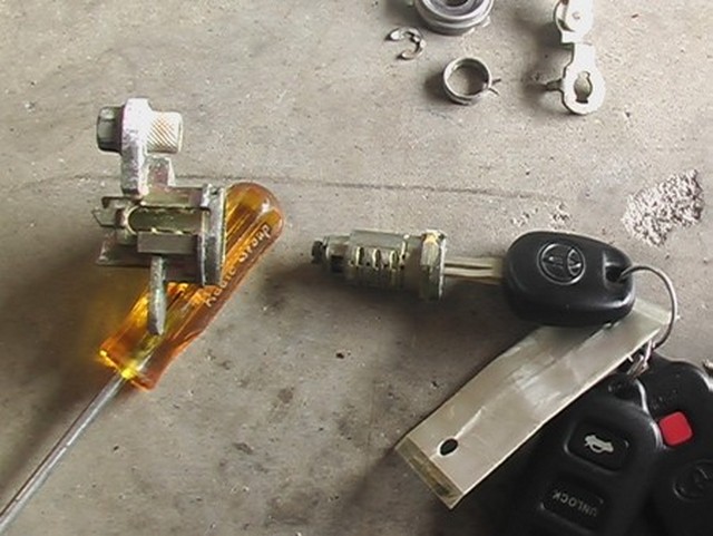
The key cylinder for the Solara comes out in much the same way but as you can see looks different from the Corolla.
Start by prying off the outer ring.
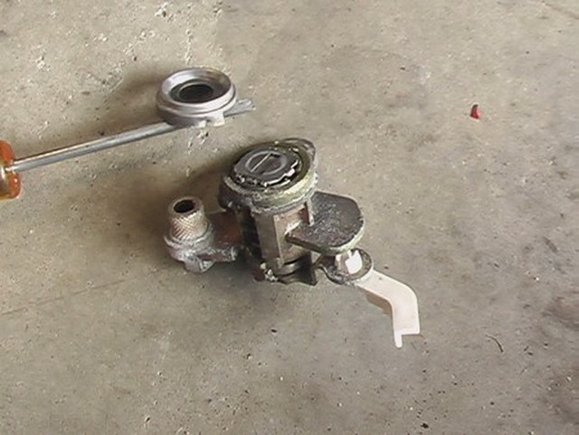
Then remove the C-clip.
The little arm comes off.
You can see the tumblers inside. These are specific to the key you are using.
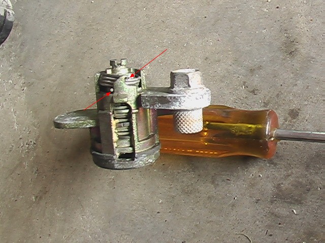
Then the little spring comes off. You can see how the ends are secured (red arrows).
Finally the inner cylinder comes out. This part simply slides into the Corolla lock.
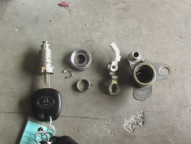
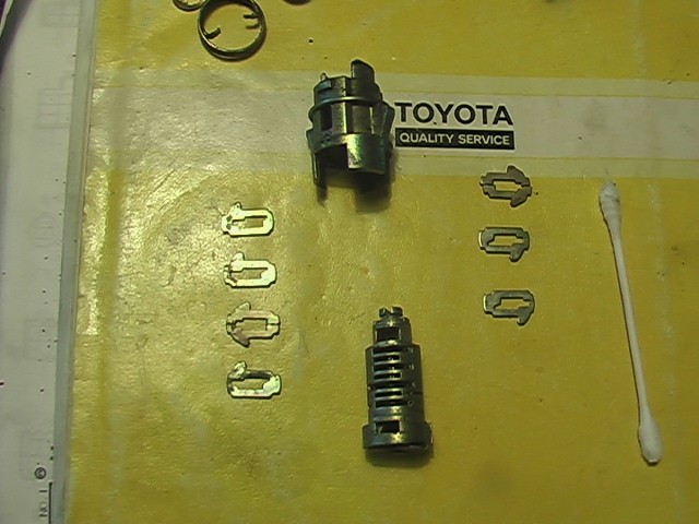
Here are all of the pieces.
As I said, just insert the Solara lock innards into the Corolla lock housing and put everything back together according to the Corolla method and the door locks have been changed.
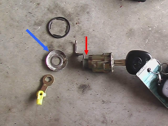
The trunk lock was of similar design but had one issue. The part with the blue arrow is decorative and wraps around the back of the lock and therefore had to be peeled away. I have no idea how to get this back on. Carefully, I imagine. I haven't tackled this yet. I can't remember what the red arrow was for.
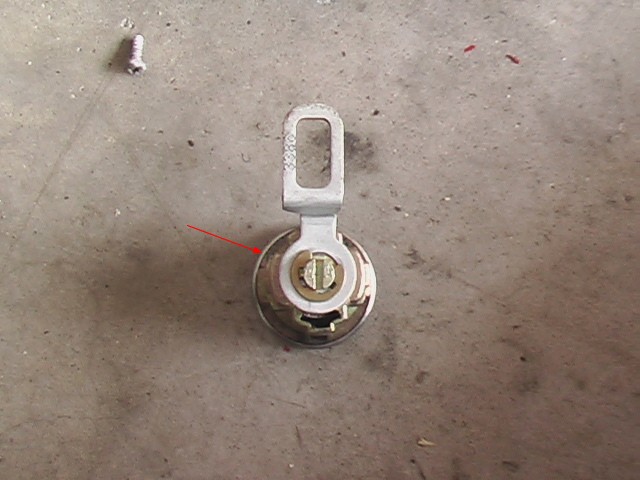
Here's what it looked like on the back side before I peeled it away.
September 5, 2016
All of this was the easy stuff. Both the Corolla and the Solara came with automatic door locks. Of course, the Corolla did not have a key fob and only operated the locks when the key was inserted in the door lock. But except for the transmitter and receiver all the necessary hardware was present. Well there was one other thing missing. Here's the hybrid schematic.
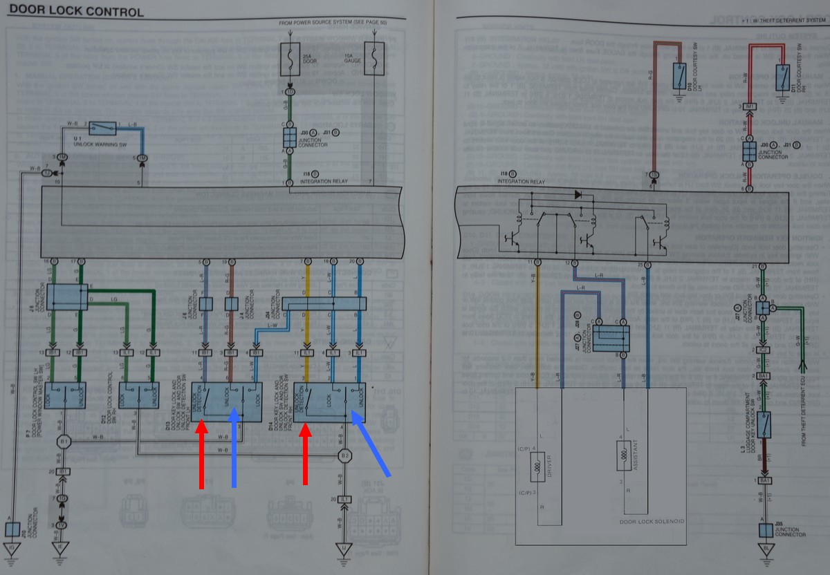
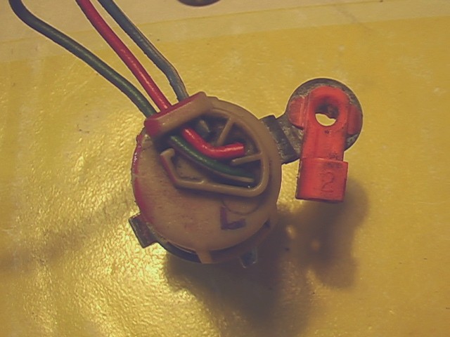
The switches marked with the red arrows don't exist on the Corolla. But it doesn't seem like it would be hard to add them. On the other hand, the switches marked with blue arrows do exist, but in my case are broken. They are no longer available from Toyota and they are so customized, I cannot find a generic replacement part. I'm going to have to science the shit out of this, to quote my favorite book, "The Martian."
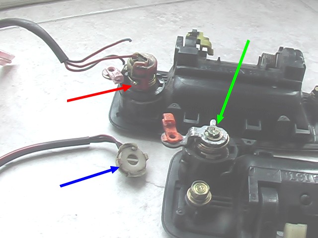
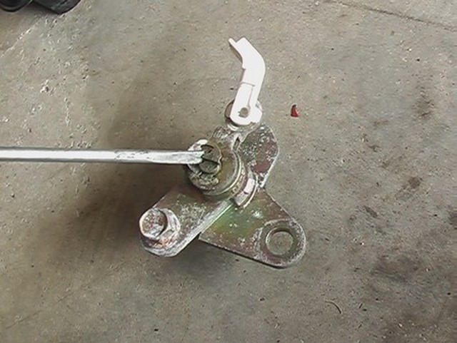
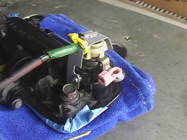
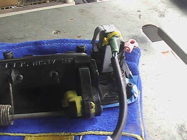
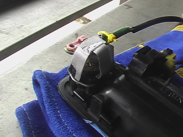
This picture shows it all. The top door handle still has the switch installed. The switch has two little arms that come down and grab a ridge on the cylinder (red arrow), but as you can see two of the wires have broken off. The copper has become brittle over time. I cannot solder these back on, because of the way they are designed. The other one still has the wires connected, but the two little arms have broken off and won't stay attached to the cylinder (blue arrow). You can see that it has a detail on the underside that matches the slot on the cylinder (green arrow) so that when the cylinder is turned either locked or unlocked, so is the switch. These are pretty cool but I don't see how to use them in their condition and creating something like that from scratch will be difficult. I'll have to come up with another solution.
December 17, 2016
Work has slowed way down on the Corolla, which is annoying. I really want this to be my daily driver. Most of the electrical stuff I've done doesn't really lend itself well to what visitors to the website would want to see, I imagine, so I haven't been updating. Here's a little of the work I've done.
I disassembled the tumblers of both locks, cleaned them and lubed them so they would be smooth. You have to be very careful to put things back in exactly the right order or your key won't work!
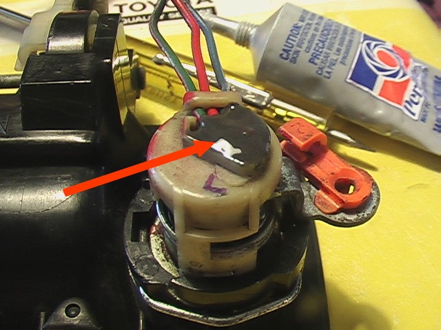
As it turns out, I was wrong about reusing the old switches. My solution to the door lock switch problem was indeed to fix them. The wires that were broken and could not be soldered actually were solderable. They were soldered inside the switch, so I desoldered the broken wire, cleaned it up, stripped back the old wire until it looked good, and resoldered it. That fixed one of them.
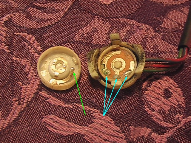
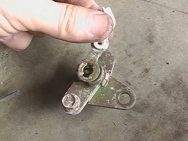
This is what the inside of the switch looks like. When it's assembled, the little tab with the green arrow moves to one of the blue arrow locations depending on lock position. You can see this switch is the one missing the tabs that hold it on.
Once I fixed the inside, I had to "pot" the wires. All that means is adding some epoxy to the back side to help hold things together.
This is what it looked like before potting.
The other door lock was far more challenging. I could probably dedicate a whole website to just this lock, so I'll try to nutshell it for you. I tried to tap the plastic so I could secure something with a screw, but that didn't work, so I wound up gluing a nut to the body of the door handle.
This is the finished product. I'm not real happy with it, honestly, but I do believe it will work. I hope it will work long term.
Here's another pic.
One side just has a hook to attach it and the other side is secured with the screw I mentioned earlier.
The reason this is important is because it completes another part of the electrical wiring system. I can now connect the door locks up to the rest of the electrical system and move along to the next part. When the electrical system is finished I can, in turn, move along to the next challenge. I hope that one day, I will tackle the last challenge and start the car. Wish me luck.
Engine and miscellaneous systems
July 4, 2016
Today I solved something that had been bothering me for a long time. I didn't know how to route the engine wiring into the cabin and to the ECU. There just didn't seem to be enough room under the hood with the supercharger pulley and other items so nearby. Then, where there was room, there didn't seem to be room inside the car due to the air conditioner. I finally found pretty much the only place it would work. I drilled a 2.5" hole in this spot and used the rubber grommit from the Solara wiring loom. I think I found the best compromise.
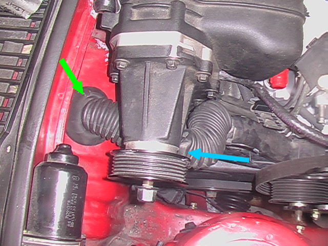
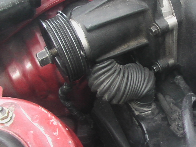
Here's another shot.
November 17, 2023
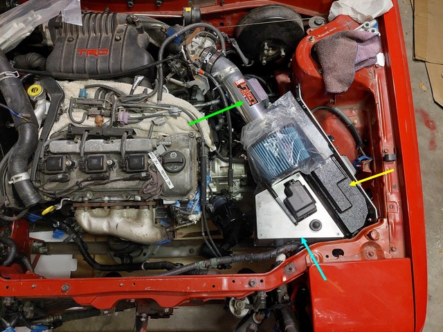
Because the Solara is a bigger vehicle than the Corolla, there was a lot of spare wire that had to be situated. Rather than leave it bundled up in the corner of the engine bay, I made this aluminum box (blue arrow) to hide it in. In order to keep the access to the individual fuse box, I made a cutout in the box top for access. I'm sure it won't be the only box like this. You can see that I lined it up with the "not so cold" air intake and the Solara fuse box. The aluminum support on the right holds both the fuse box and the igniter.