
Interior
Dash
November 6, 2011
The dashboard is made of a number of layers of plastic and foam and it has a texture on it that makes it difficult for me to work with. I'm not very artistic. So as long as the dashboard was in good condition, I did not do anything to disturb that equilibrium. After about 20 years in the hot Florida sun, however, the dashboard finally cracked. Once this happened I decided I didn't have anything to lose. Nothing I did could really look worse. . . I hoped.
Once I started planning, I decided to create a whole new dashboard of my own design. And as I got into it, it became clear that the dashboard was primarily going to be composed of speakers. I wanted a good sound system and I didn't want the sound down by my legs. I got a lot of my car stereo info from a website called DIY Mobile Audio. DIYMA
Much of the rest of the dash was taken up by the AC unit from the Solara.
The Solara AC unit is built a little differently than the Corolla unit. Even though the Corolla unit is built for the car and therefore fits like a gem, I decided to go with the Solara AC unit because I planned to use the R134A refrigerant in the Solara AC system, as it was designed. The Corolla system had three components: the AC unit which houses the evaporator, the blower, and what I'm going to call the diverter because it's job is to divert the airflow to where it belongs. The Solara system has only two parts: the AC unit with integral diverter and the blower. I will use the AC unit from the Solara and the blower from the Corolla.
Unfortunately, the AC unit from the Solara is considerably larger than that of the Corolla, and placing it in the center of the dash means that it will occupy the same space as the lateral support under the dashboard. Here's how I handled that.
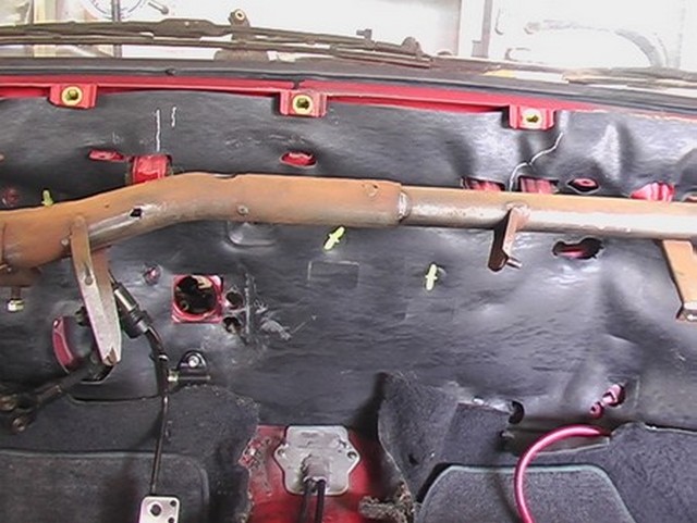
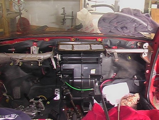
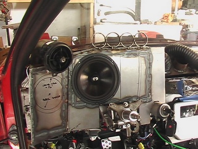
Here is the rusty stiffener that sits behind the dashboard. With the support out of the car I located the AC unit where I wanted it and marked the car for the cuts. See the white chalk marks on the black pad, upper left?
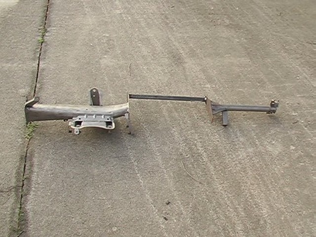
I cut the lateral support. This will kill the chassis stiffness, you are probably thinking. And you'd be right. I had to put something back in.
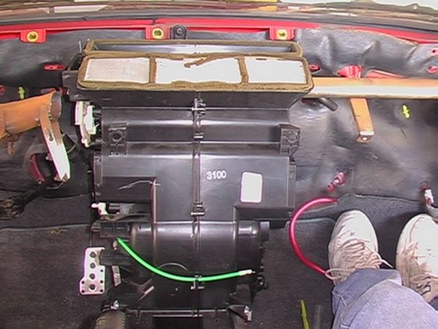
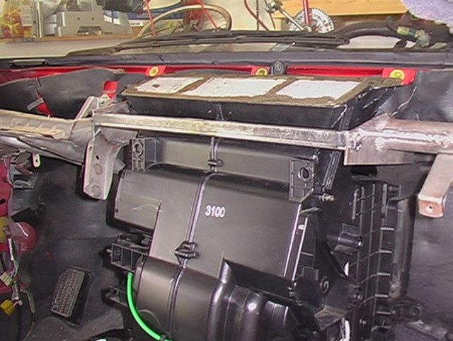
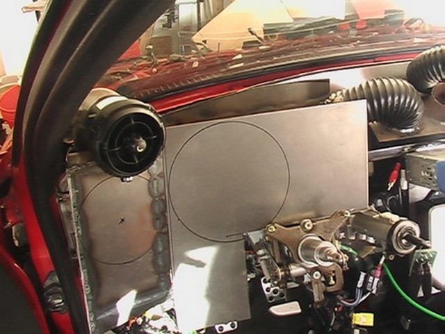
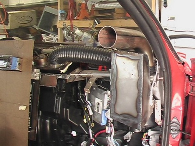
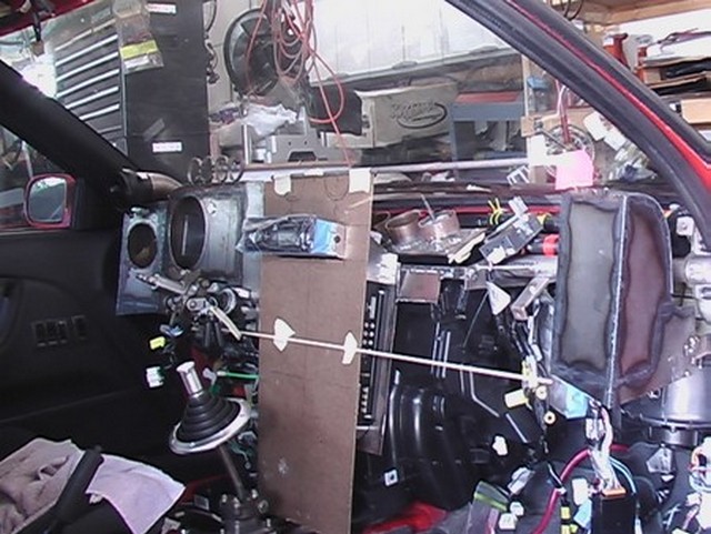
Here I have installed the AC unit. Well, actually it's just sitting there. It isn't really installed yet. Unfortunately, the Solara ac unit has to be offset to the passenger side because it is too wide to sit in the center without interfering with the pedals.
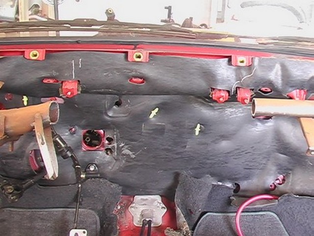
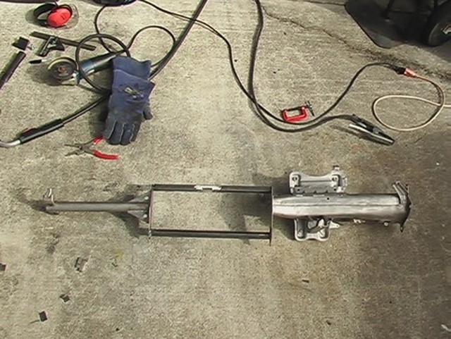
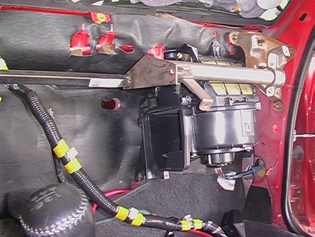
I welded in this bar, which runs behind the AC unit. There was barely enough room to do this and still have the AC unit fit up against the firewall. It took a lot of eyeballing to get it right. A second bar is bolted in front of the AC unit so that the AC unit can be removed if necessary.
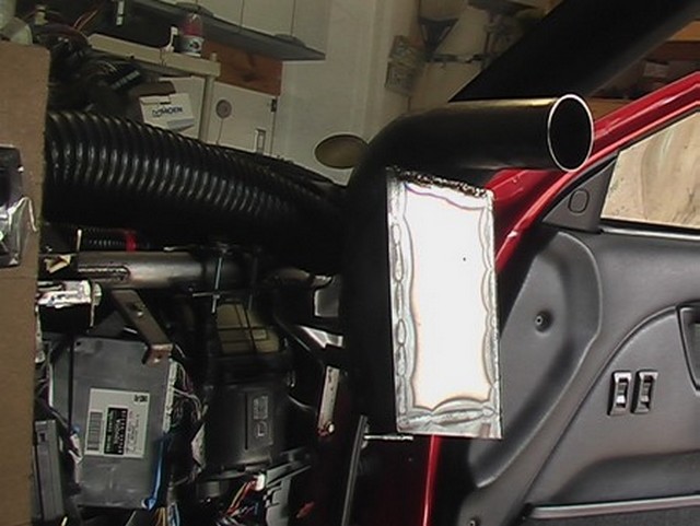
Here it is with the AC unit in place.
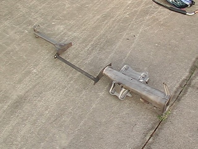
Here are some pics of the cross member out of the car.
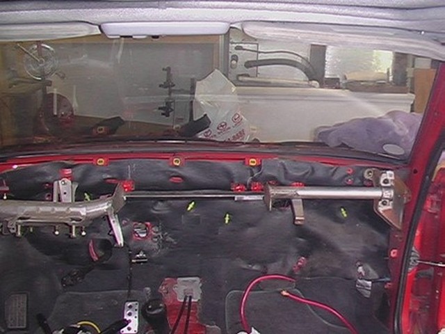
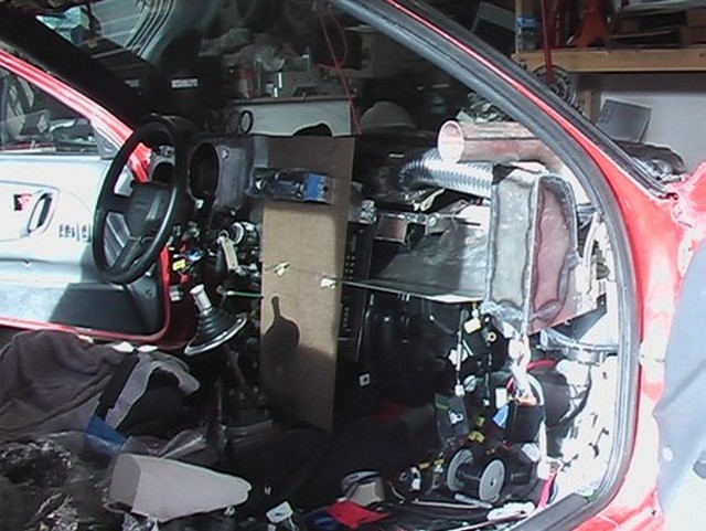
Here's what it looks like after it was reinstalled in the car with the AC unit in place. I'm not done. There is more stiffening that takes place. This was just to get the big pieces in place so I could figure out how to get everything to fit.
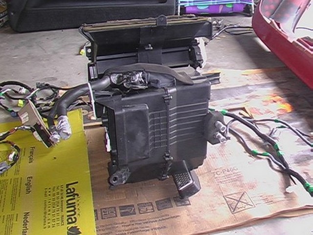
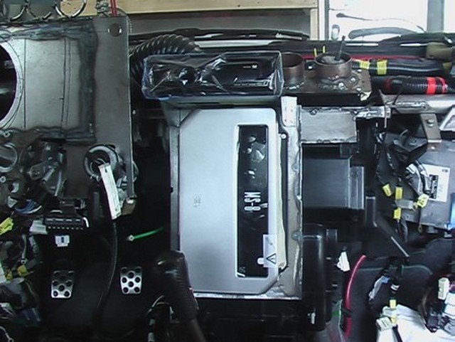
To make sure I didn't miss anything and for future reference, I took a picture of the back side of the AC unit.
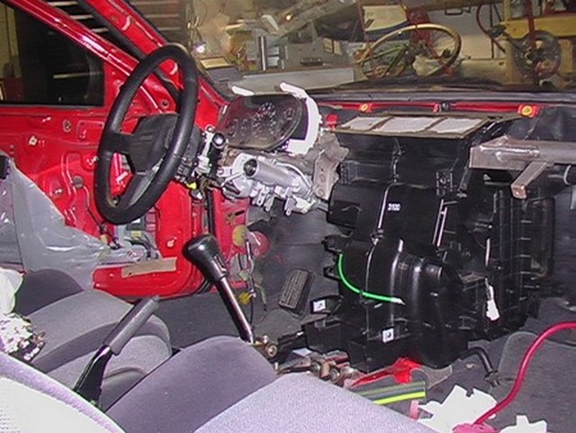
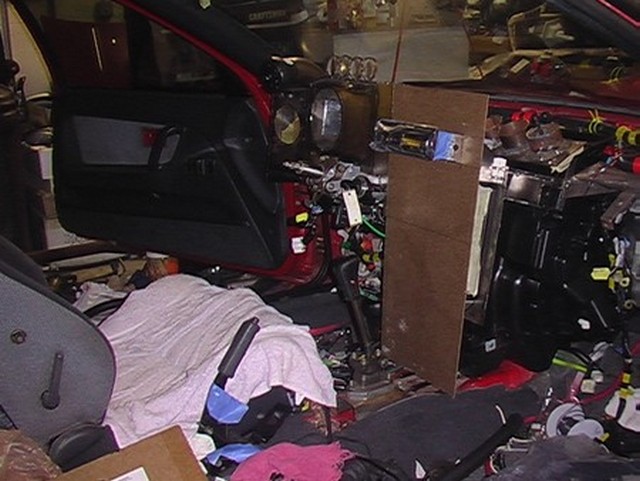
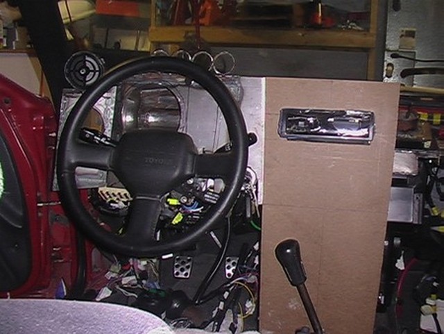
To make certain I didn't run wires over the pedals or something stupid, I installed the clutch, brake and gas pedals and of course the AC unit.
I have the Solara gauge cluster on the steering column in this picture, but I have a totally different plan now.
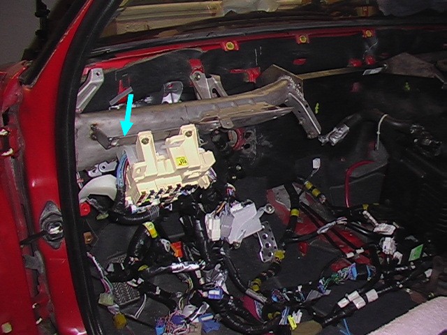
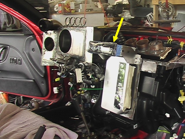
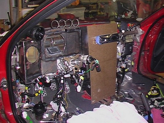
I discuss the electrical wiring in the electrical section, but the dashboard really can't be considered all by itself. The wiring determines where a lot of the controls are located. The blue arrow in this photo points out a little bracket I welded onto the lateral support. You can see that I mounted the fuse box here.
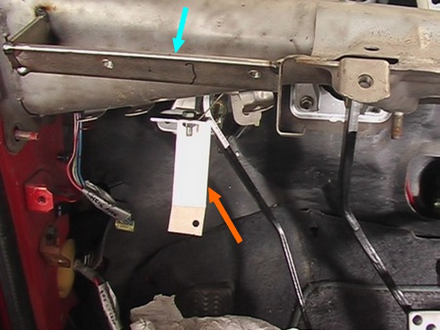
Here's a closer picture. The blue arrow points at the bracket I welded in and the orange arrow points at an aluminum bracket I bolted in to hold the fuse box from below.
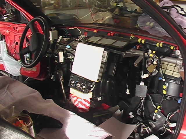
Here's an early concept of a dash layout. The white paper in the center stack represents the car computer, the ac controls are below that and the red box below that is just to hold them up.
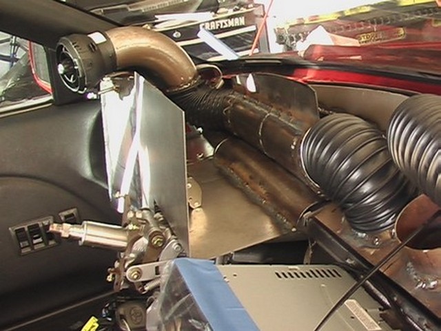
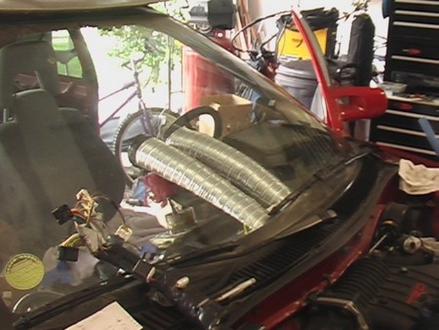
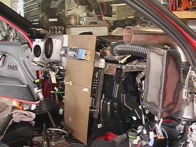
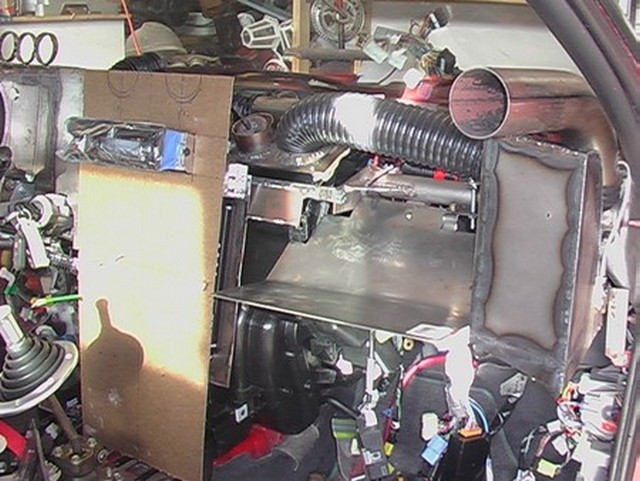
Another major component is the blower. This is the stock Corolla blower housing, with the Solara motor, in the stock location.
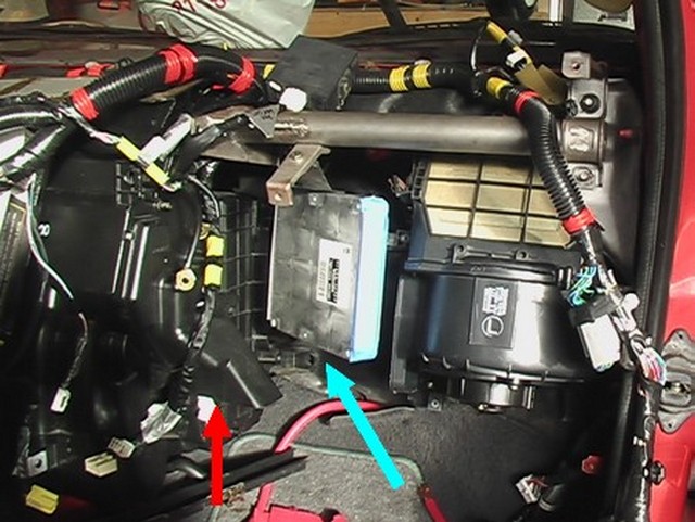
The ECU (blue arrow) goes between the blower and the ac unit. It's at an angle because there is a duct that goes from the blower to the ac unit, so the ECU cannot mount to the firewall.
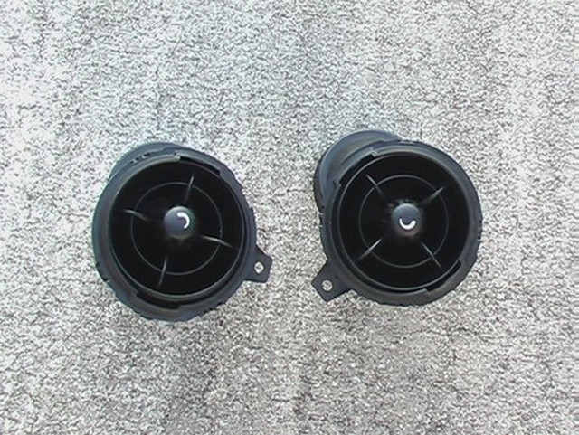
Here are the ac vents I plan to use. I looked all over the internet and most of the vent designs I saw were boring square things or were molded to fit a specific dashboard. These seemed like the best looking ones I could find that would get the job done. They weren't too expensive and it has the control for the direction and volume of air flow built in. They are from a 2010 Mini Cooper.
August 2, 2012
Ok, here's where the lines start to get blurry. Because most of the dash is composed of speakers, I can't really discuss the dash without discussing the speakers. So here is where I start building my stereo system. I'll try to keep the stereo discussion here to the mechanical part and the electrical portion will go in the stereo section of this website.
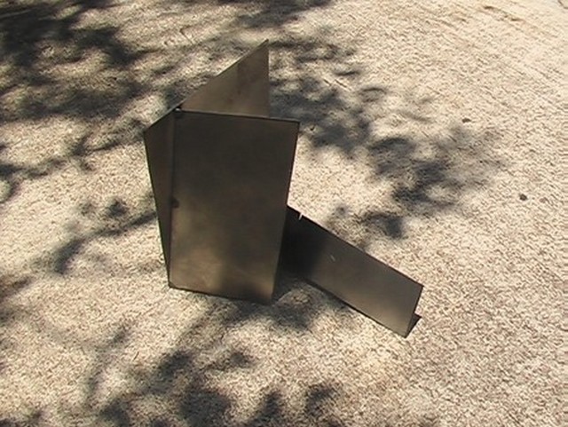
I've never had a high end stereo in my car. I just used the one that came with it. It still worked after 20 years and I just kept using it. Now that I'm reinventing my car, I decided this was the time. So after doing some research it appeared, in order to have the correct amount of space for the speakers to function, there wouldn't be a lot of room for anything else. So the dashboard was a result of me trying to figure out how to provide the correct amount of volume for each speaker in the confined space of the car. It meant that fitting other things in was much more difficult than I thought. Here are a series of pictures of the construction of the first speaker. It has an odd shape.
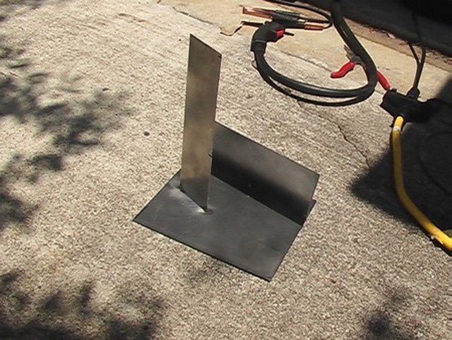
For the midrange speakers, I was told verbally by CDT that they only needed to be a little larger than the speaker. It sounded like this was a lower limit, so I made them a little bit bigger. A buddy of mine who knows a lot about the subject thought they looked big. He managed to find some data sheets on the speakers I purchased. CDT's website just gives you an error when you try to surf to it, but we were able to find it by doing a web search. As it turns out, this is almost exactly the size in the data sheet. Guess I got lucky.
The speakers that go in these boxes are 4" drivers from CDT and require 0.05 cubic feet. Here's the link to the data sheet: http://www.cdtaudio.com/pdf/HD-4_07.pdf
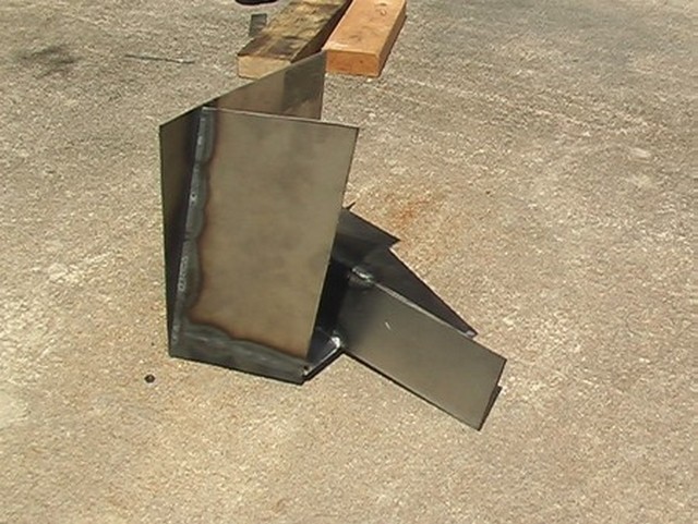
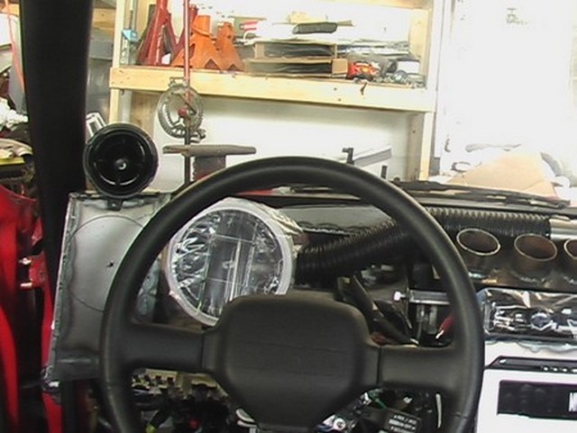
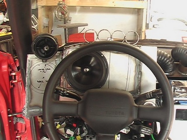
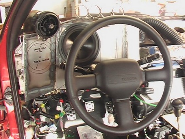
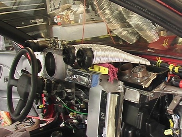
The speaker has that curved shape because I wanted to have my ac vents come over the top like periscopes. With the left mid-range speaker box in place, you can see how the vent will go. I like this arrangement because the air conditioning often blows right on my hand when I drive. This will put the vent above my hand so my fingers won't freeze anymore. It's what Reddit would call "a first world problem."
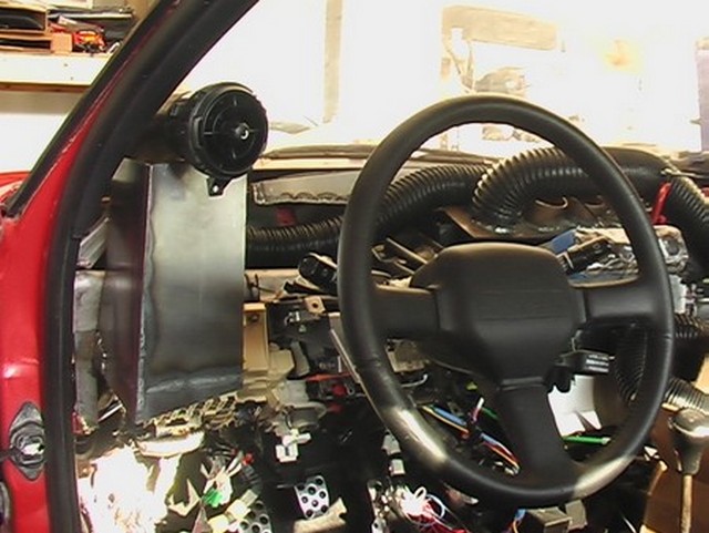
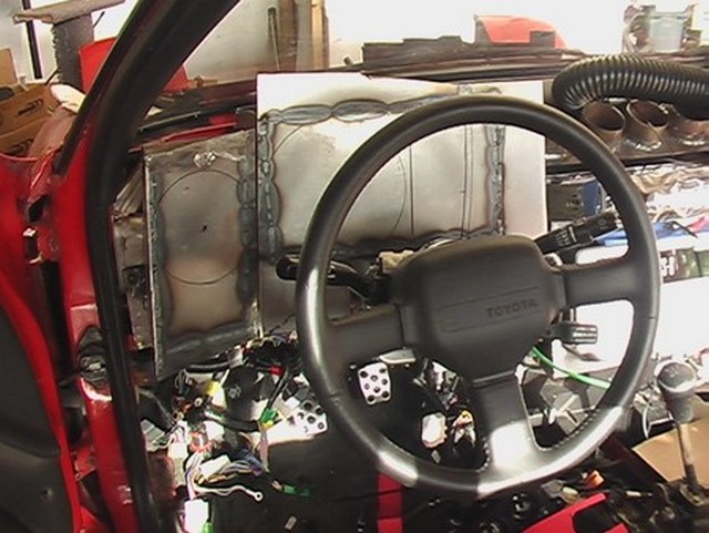
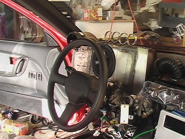
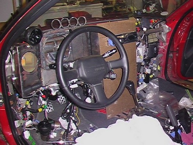
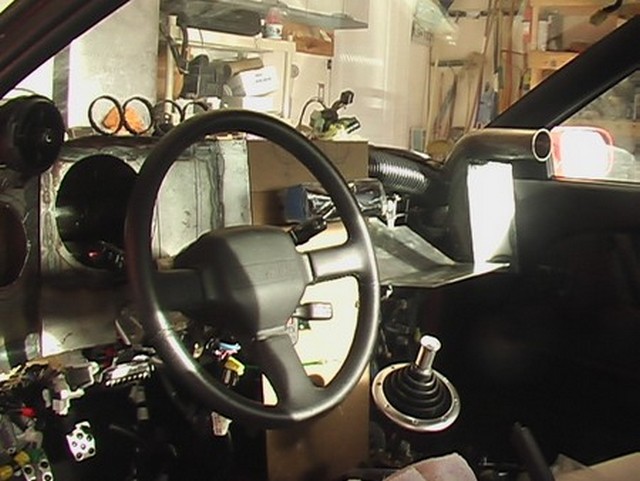
Looking through the steering wheel, you can see the midrange speaker box on the left and I have placed the woofer roughly where it should go. It looks weird because it is still in its plastic baggie. This would be a good location except the speedometer and odometer will mount on the steering column and block the woofer. After careful consideration, I decided that I would just have to live with it.
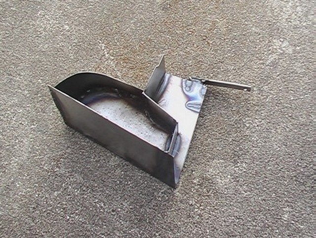
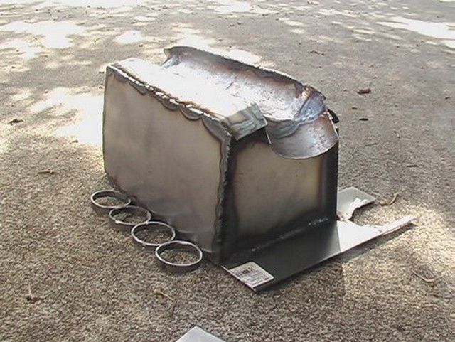
So I started working on the speaker box for the woofer.
This is the part that faces the driver. As it turns out this box has to be 0.30 cubic feet, which takes up virtually all of the space in front of the driver. Originally this is where I had intended to place my gauges. So I had to come up with a new plan.
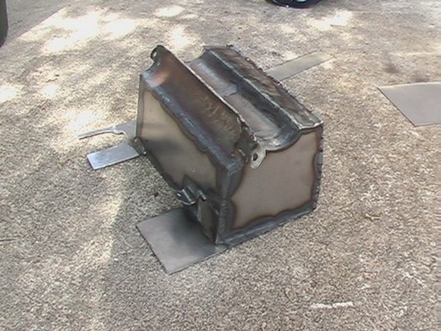
Getting the line between the midrange and the woofer boxes consistent was tricky, but I think it came out pretty good.
Here is the link to the specs for the speaker that goes in this box: http://www.cdtaudio.com/pdf/HD-6_07.pdf
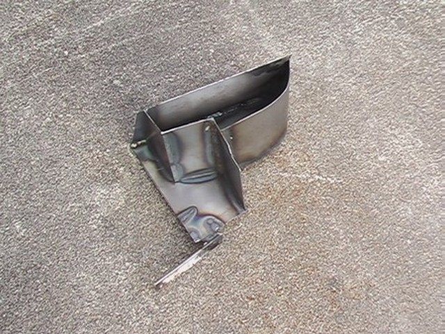
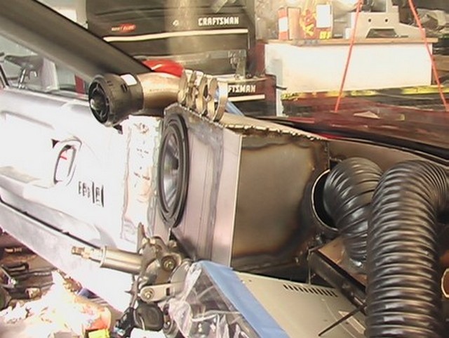
This is a view toward the driver's side. You can see that I have the black air conditioning hose going from the center output to the periscope duct on the left side. Then I have formed the metal of the speaker box around it. The volume is a little low for this speaker, about 0.25 cubic feet, but it's the best I can do with the size of the vehicle.
Here's another shot.
I added a little to the face of the speaker box at the top because I was afraid the speaker wouldn't fit. Word to the wise. . . plan ahead!
And another view.
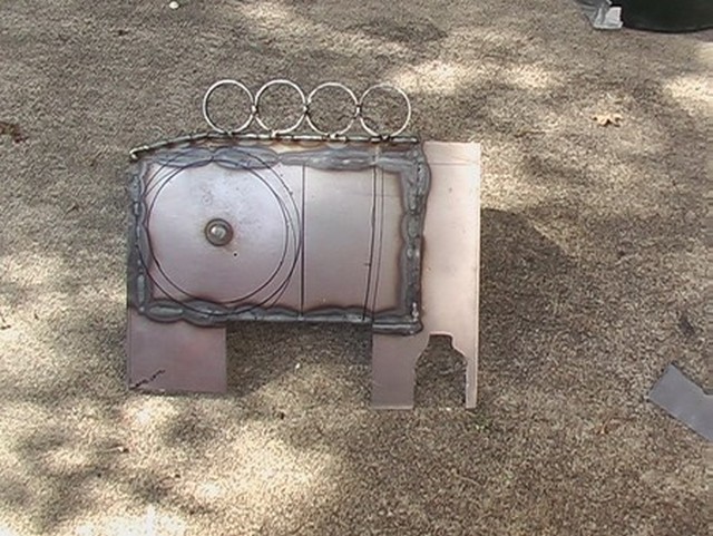
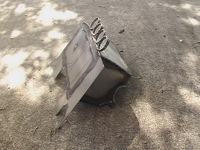
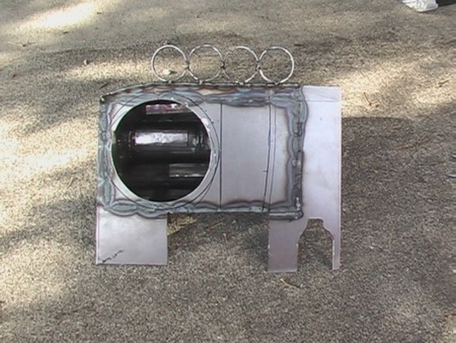
The following group of pictures shows the nearly finished product. It just needs the hole for the speaker cut out and a little hole to run the wires. I have tack welded four rings onto the woofer box to show where the gauges might go.
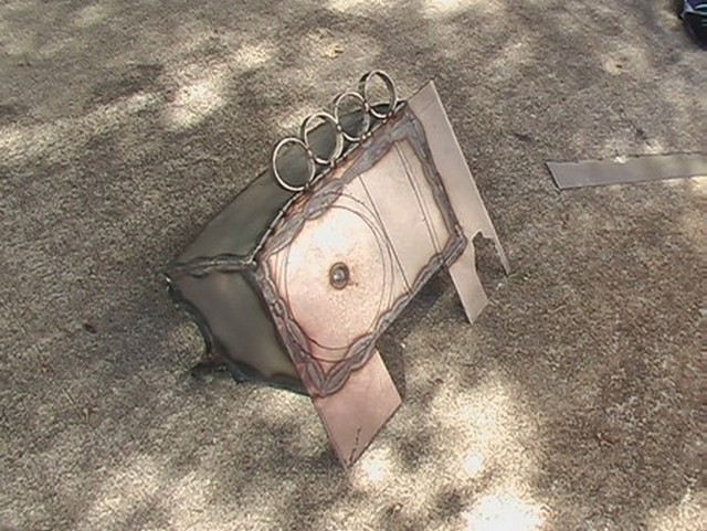
Here are some pics with the hole cut out. Inside you can see the CTL material I used to dampen the sound of the metal enclosure.
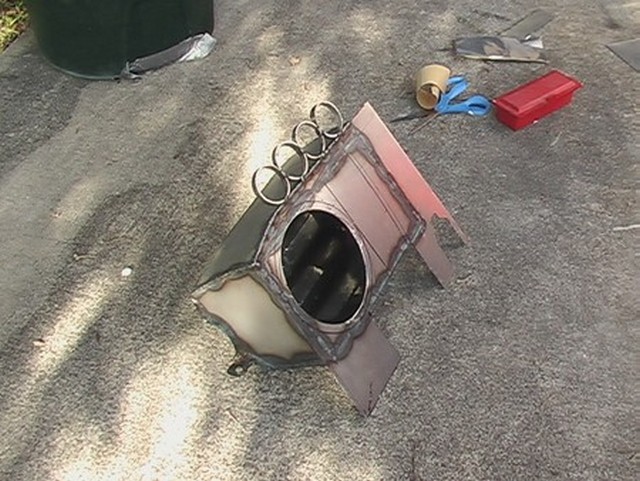
And finally, here it is mounted in the car. I've temporarily put the speaker in so you can get the idea.
August 11, 2012
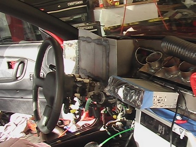
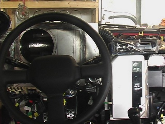
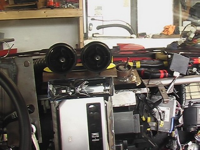
I know it's hard to see what's going on in this picture, but you can ignore most of the clutter. On the left is the mid-range speaker box, with the hole for the speaker cut into it now. Next to that is the woofer, with the "gauges" on top and the yellow arrow points to the radio over the top of the MS-8, which is a Digital Signal Processor that will help with sound quality. The radio doesn't look like a radio because I put a piece of plastic over the front to protect it. It is held in place with blue tape. You can see that there is an angled bracket that holds the radio in place. Things will become clearer in the following pictures.
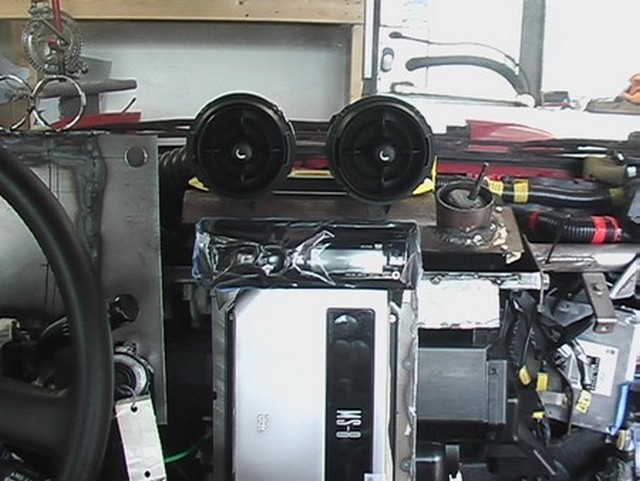
Here are a couple more pics. Maybe it will help with seeing what's going on. The radio is right next to the steering wheel at the 2:30 position.
I was trying to get an idea of where to place the ac vents in the center column. Below you can see some options. I'd like to put a clock between them, maybe the old clock from the Corolla, just for nostalgia's sake. I think I like the placement in the second picture the best.
I toyed with the idea of having some pipes come straight out from the dash to hold the center ac vents in, but ultimately rejected the idea. Something like this:
Moving from left to right, brings me to some sort of face plate for the center console. I think you can see better how things are shaping up, especially in the last picture.
August 14, 2012
I was still thinking through the center stack, but I knew what the right side speaker boxes look like, so I started moving from right to left. Here's the right side mid-range speaker box. It was a lot easier building this one than the last one, because I didn't have to figure it out. I just copied the other one. Getting it in the right position was kind of difficult though. And in fact, I got it wrong and had to space it up a bit.
Here are some more pics. In the last one you can see I put a couple of wood strips across as a reference.
After I finished that I started on the passenger side woofer. This one is shaped a little differently than the one on the driver's side, but should have about the same volume. Here are the pics.
October 20, 2012
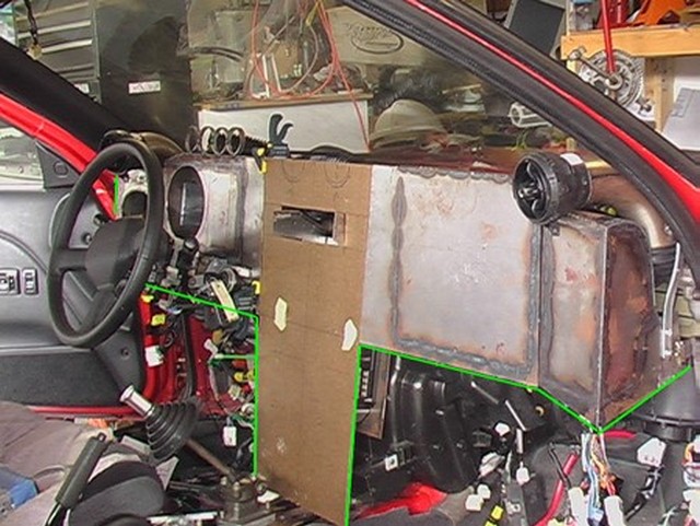
Here's a picture I hope will make it clearer. I have all of the dash mocked up. I outlined it in green for you.
April 5, 2013
There is a big break between the picture above and the picture below, but I was working a sand blasting box and my trick twin shift lever design (see other sections of this website).
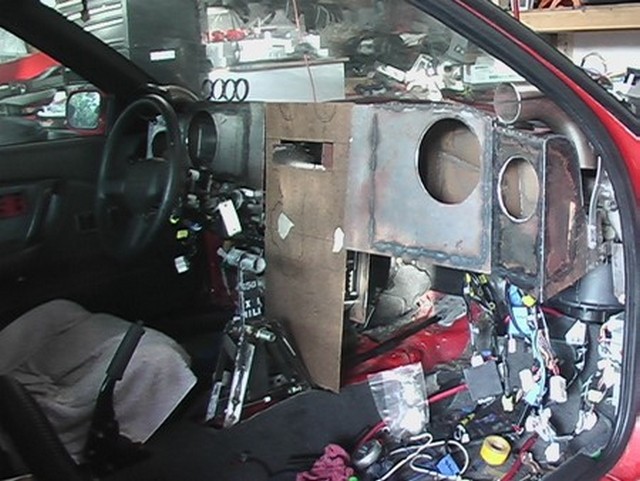
The only real difference is, I've adjusted the height of the right side speaker boxes and put the holes in for the speakers.
To be continued. . .