
Brakes
Front Brakes
December 29, 2007
Big brake upgrade!
The brakes on my car were sort of funky. I never really noticed anything wrong with them for the most part, but I think you sort of get used to things and then you are no longer objective about them.
I was having some service done to the car somewhere and when I went to pick it up, the mechanic said something like, "Oh the one with the funky brakes." I didn't know what he meant, but later, I checked the brakes and the front brakes had about 20% of the pads left and the rears had roughly 95% left. So I started thinking, gee this is weird, did I just change the rears last time?
I decided to change them all and bleed the system. During the process I had my roommate apply the brakes while I torqued the rear wheel on. As I tightened, the wheel started to turn. So I asked her to step on them harder. She did this, but the wheel still turned.
"Harder," I yelled.
"I'm stepping on them as hard as I can."
"Really?"
So, that didn't seem quite right to me. Even a small woman should be able to lock the brakes easily. Over time I replaced the rear disks, the calipers, the brake master cylinder, the proportioning valve, and the pads. To my reckoning, other than the brake lines this was everything between the pedal and the disk, but still I had virtually no rear braking. I went online and purchased some steel braided brake lines from Technafit, but before I installed them, I purchased a new car and the Corolla began it's long sleep.
Fast forward about 4 years when I started doing my overhaul and here I am addressing the brakes again. I have heard, I think it was Stop Tech that stated this on a TV program, that bigger is not always better. Well, sure if the system is poorly designed, the master cylinder is not sized properly, etc, maybe, but I believe and Fred Puhn who wrote "Brake Handbook" agrees, that you should stuff the largest disks that will fit inside your wheels.
Naturally, I began searching for a big brake kit for my car. Yeah, right, performance parts for a Toyota? In America? For a Corolla?
There are some generic kits out there, that might be adaptable but the cost was outrageous and none of them were a bolt on kit. So I started researching, thinking along the lines of the GTZ brakes from overseas. But you can't just put larger disks on. If you do that, you have to move your calipers outward to compensate, which meant coming up with a mounting bracket, etc. I needed something I could get my hands on. Eventually I stumbled upon Brembo's fantastic website. You can find them at, you guessed it, www.brembo.com.
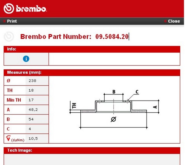
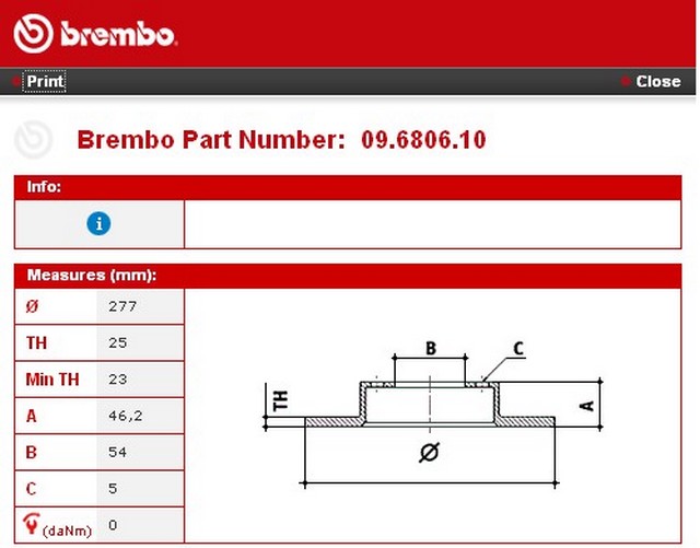
It was great because they showed all of the dimensions for all of their brakes. So all I had to do was look for the corolla brakes and get all of the dimensions. Then look for a brake disk with similar dimensions, but larger diameter. Once that was done, I could figure out what car it went on and then see if I could put the parts from that car onto mine. And surprisingly, it worked!
Regrettably, Brembo no longer shows these dimensions on their website anymore.
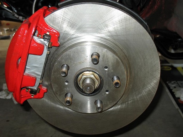
This is what they had for my Corolla.
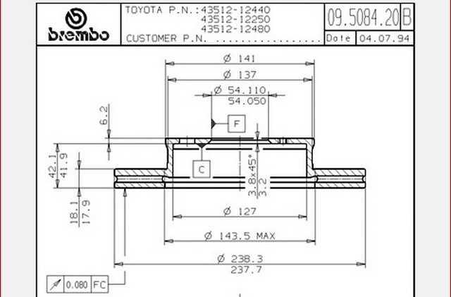
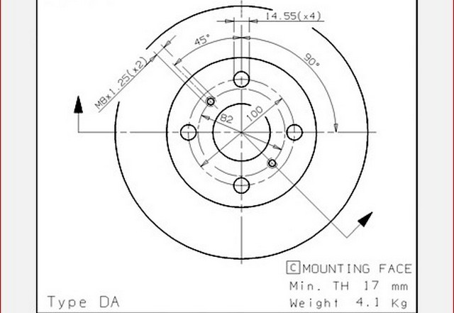
I found a few disks that were similar, but only a tiny bit bigger, not really worth the effort. But then I found this one. It was significantly larger and it came off of a Celica.
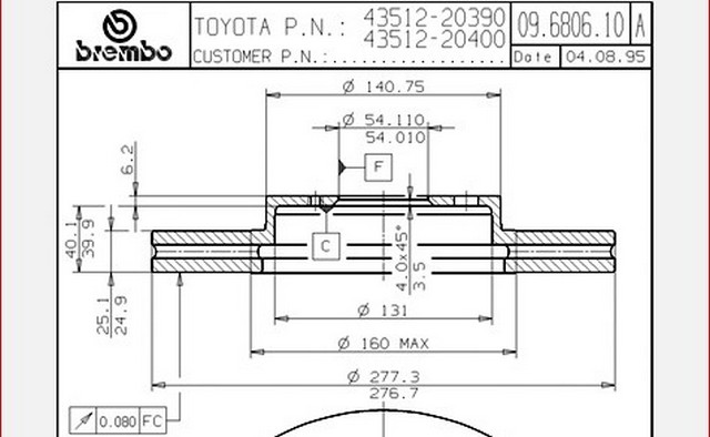
You may notice a few problems with this disk. It is a 5 lug disk and the dimensions are all different. But it is over 1.5" larger in diameter. It's also quite a bit heavier. That's not good for handling, but it is good for braking performance. To me it was worth taking a look at a Celica.
I can tell you that the fronts weren't too hard to change at all. But the rears took a bit of work. Plus the emergency brake was a problem.
To use these front brakes you will need the following parts:
-New rims and tires
-Hubs from a 1991-1993 Celica GTS (I believe the GT works as well).
-Calipers from a 1991-1993 Celica GTS
-Mounting bracket from a 1991-1993 Celica GTS (also called a torque plate)
-Dust shield from a 1991-1993 Celica GTS
-Discs from a 1991-1993 Celica GTS
-2mm spacers
-Brake pads from a 1991-1993 Celica GTS
I recommend replacing the wheel bearings at this point. The wheel bearings for a Corolla fit and the extra weight in the front isn't that significant when split between both front tires. They are pressed in, so you might need to take them to a shop.
The brake lines from the Corolla fit, but again, I think this is a good time to replace them.
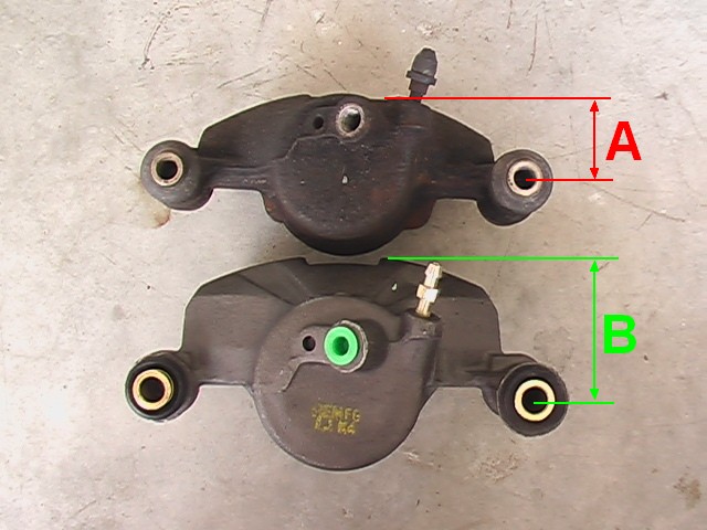
You can see there are differences between the Corolla and Celica calipers. I have driven the car with the new set-up and I don't believe it is necessary to replace the master cylinder as of 02/21/14. However, the rear brakes are still a little weak and I plan to replace the proportioning valve. This situation may change.
I should also mention that there are theoretically some handling and performance trade-offs involved. The Celica brake rotors are almost twice the weight of the Corolla rotors. This is referred to as "unsprung" weight and is bad for handling. It will also add weight which the engine must overcome with extra torque in order to accelerate the car as quickly as it did with the smaller weight. Because this weight is in the driveline, its effects are magnified. I have read that adding a pound of weight at the wheel is equivalent to adding 3 pounds of weight in the cabin and that adding a pound of weight in the driveshaft/clutch area is equivalent to adding 15 pounds of weight to the cabin. I have also heard different numbers quoted for this, so I think it is most important to take home as a guideline that adding weight to the driveline is a bad thing and that it gets worse the closer you get to the engine.
However, as far as braking goes, the news is much better. The increased diameter means more braking torque and the heavier rotor means that more energy can be dissipated in the form of heat. Because the rotor can handle more heat, it also means that "boiling" of the brake fluid should be minimized and brake fade lessened. The great thing is for all intents and purposes (except the master cylinder) this system was designed by Toyota. All I'm doing is retrofitting it to a lighter car
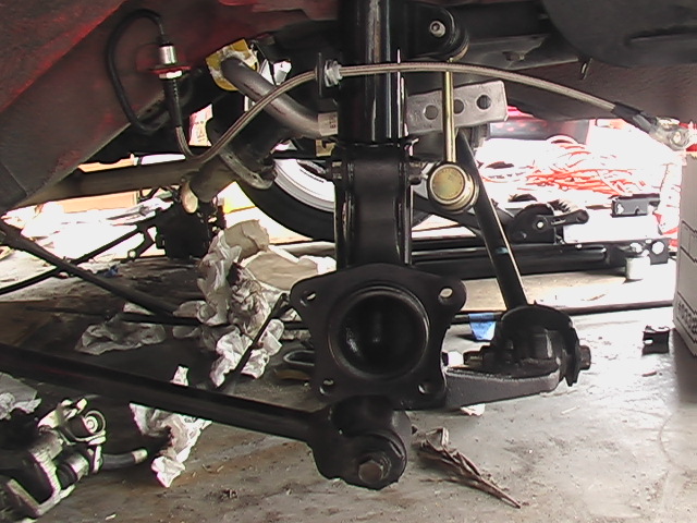
With dimensions so similar to the Corolla's I began to think that the Celica probably shared more things in common with the Corolla. So I went to a junk yard and took a look at a 1992 Celica GTS. The front suspension looked almost exactly like the one on my car, so I bought two whole brake assemblies including the spindles and hubs. I disassembled both the Corolla and the Celica brake assemblies to make measurements. This required having the hub pressed out of the spindles. Shop around, this was ridiculously expensive for such a simple task. One place wanted to charge $40.00 per hub, another did it for free as part of the consulting process on how to do this brake mod. Go figure. With all the parts disassembled I took my trusty calipers and began making measurements.
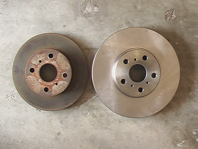
Changing to these brakes will definitely improve the braking but a side benefit is that the rotors won't look ridiculously small inside my new 16" rims.
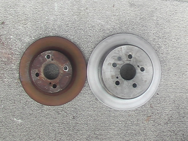
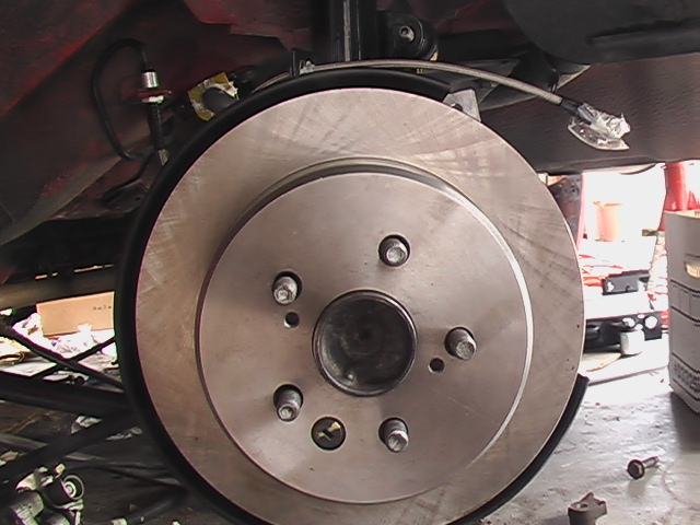
The stock Corolla rotor is 9.4" in diameter and the Celica rotor is 10.9".
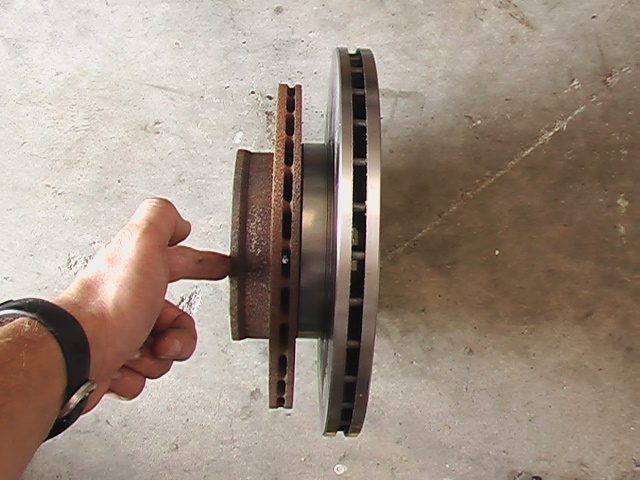
Here is the difference in thickness.
The Celica rotor actually stands up by itself due to the increased thickness, while I had to hold the Corolla disk upright.
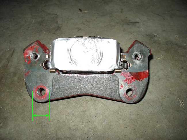
As I mentioned, if you choose this route, you have some decisions to make. Except for the Celica hubs, I bought all of these parts new. I wasn't going to use those old rusty junkyard parts on my overhaul. The cost was a bit pricy, but not any $4000.00 like the price I saw on some kits. The biggest expense of course was the new rims and tires. If you want to retain your existing wheels, then this conversion isn't for you. Also, the rear brakes required having some custom parts machined to get them to work. So if you just wanted to have larger front rotors without touching the rears, then this mod would leave you with a four bolt hole pattern in the back and five in the front. I think that is just silly.
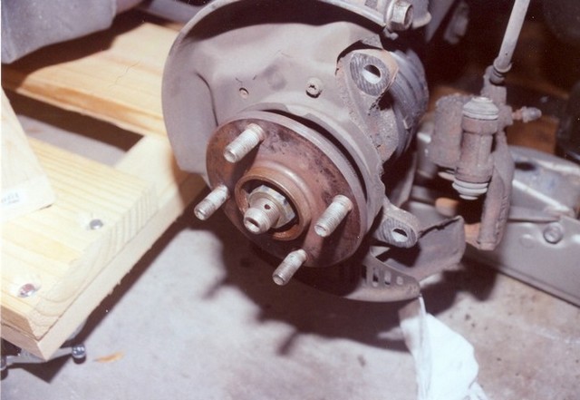
Step one in this process is to remove the hub. But to do that you first have to get that big nut off. This turned out to be a challenge. After securing the axle from rotation, I used an 18" breaker bar and 180 lbs of force (that's me standing on the end). It laughed at me. The guantlet had been thrown down. What proceeded to happen over the next weekend or two was a battle between me and this stupid nut. Cans of PBY blaster were consumed, complex contraptions constructed to both keep the hub from turning and to apply increasingly more force to the nut. There was a lot of kicking and screaming and I have to admit, some harsh language was exchanged. These efforts culminated in the purchase of a 21 gallon, 6hp air compressor and impact tool set (on sale at Sears for $300.00). Again, the nut laughed in my face. Nothing would budge this thing. So I had an idea. . . .
See that bar hanging off of my hub? I finally had the upper hand in the battle. Nothing, but nothing could withstand 180 lbs of force over 12 feet!
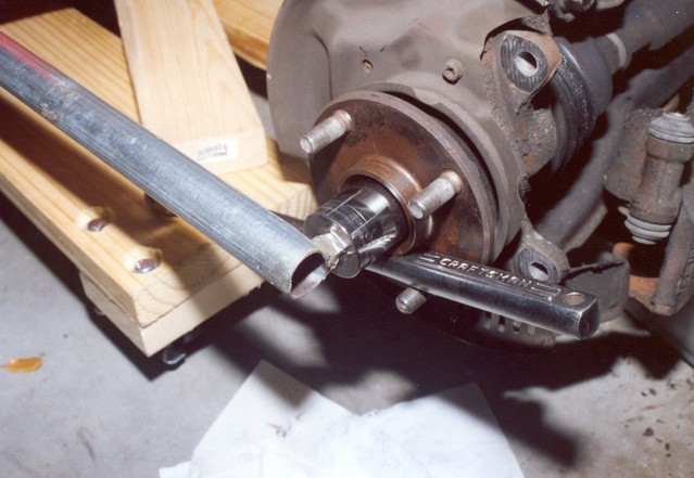
I welded a square piece onto the end of this 12 foot pipe I had lying around and put my socket on the end. When I pushed down on the other end it twisted with virtually no effort at all. Bwahahahhahaha! I win!
Unfortunately, I could hear this little tiny din of laughter coming from the nut.
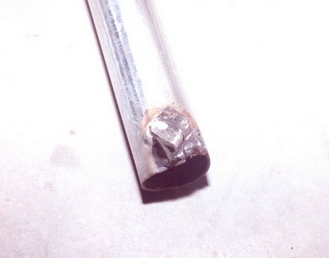
Look at this. Unfortunately mild steel is no match for that nut. I'm happy to say that my weld held up nicely.
In the end, I finally removed the nut by taking my grinder out and cutting it off, which meant I had to purchase another axle nut to do the reassembly. I may have lost the battle, but I . . . umm. . .guess I lost the war too. Damn nut!
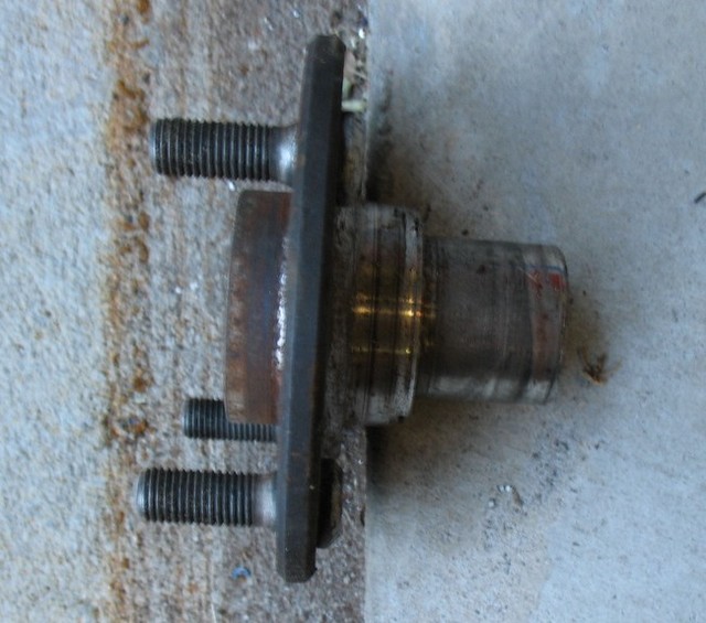
Here's a somewhat blurry picture of the hub.
I forgot to take a picture of the Celica hub. The important thing to note is that although it is bigger on the front side than the Corolla hub, the backside is identical.
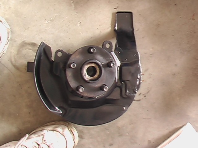
Here's the whole assembly
It is important to note that dust shield needs to be installed BEFORE the hub is pressed into the upright.
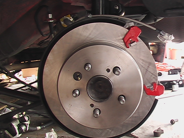
So, after you press the hub out of your old spindle, new bearings are used to press the Celica hub (with dust cover installed) into your old spindle. That's about all there is to it. You now have a Celica setup ready for Celica brakes. With the longer calipers, you'd think that the mounting bracket would be the same and this might be the case on the Celica with slightly smaller brakes, I don't know, but on this one, you also need the new mounting bracket. You might get this at the junkyard as well, but I wound up buying new ones from Toyota for some reason. This bracket has the same hole spacing as the Corolla so all you need are the appropriate bolts, calipers, spring clips and pads. All of which I purchased new. Well, there is one catch.
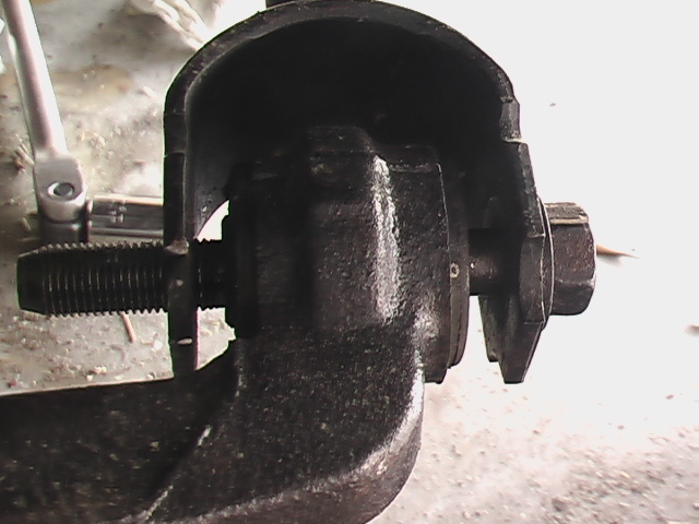
If you try to assemble the brakes like that, you may notice a slight interference problem. This caliper mounting bracket is rubbing on the disk because of the 2mm difference that was mentioned before in the disk design. So the bracket needs to be pushed outward by 2mm.
I had steel washers specially machined to 2mm to accommodate this difference because I don't want aluminum anywhere in my brake system. I also had them made to the same size as the contact patch on the caliper mounting bracket to maximize the surface area between the two. The reason you don't want aluminum here is two-fold. First aluminum expands at a different rate than the steel around it and second and most important reason is that dissimilar metals are a cause of galvanic action which will cause corrosion.
It's time for one of those disclaimers you always see on TV: Off the shelf washers may work in this application, but then again, they may not and if you choose to go to Home Depot to space your calipers, you might die and I will not be held responsible. In fact, all information on this website is informational only. Use discretion when following ANYONE'S advice.
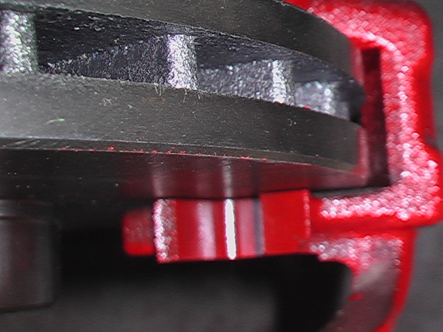
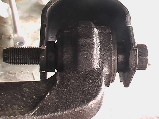
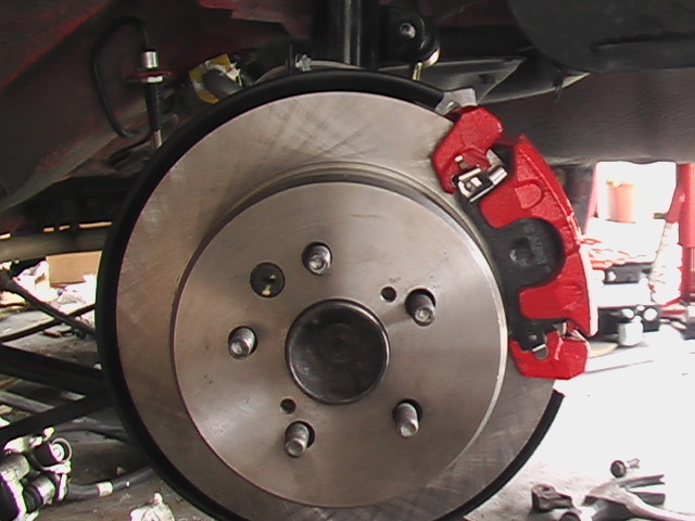
I painted the washer (blue arrow) to help with corossion. Some of the paint has come off, which is why it looks like that.
Here's a picture of where the washers mate to the caliper. You can see the paint transfer. The funky looking stuff on the brake pad is duct tape I have placed there to help keep the brakes from squeaking. I heard this works. I don't recommend it. They make stuff you can buy that prevents this. Duct tape will come off and it's messy. I have no idea if it works. The front brakes don't squeak, so maybe it works.
The brake pads are PBR Ultimate Ceramic pads. They feel good but they leave a lot of brake dust on the rims. I won't buy them again.
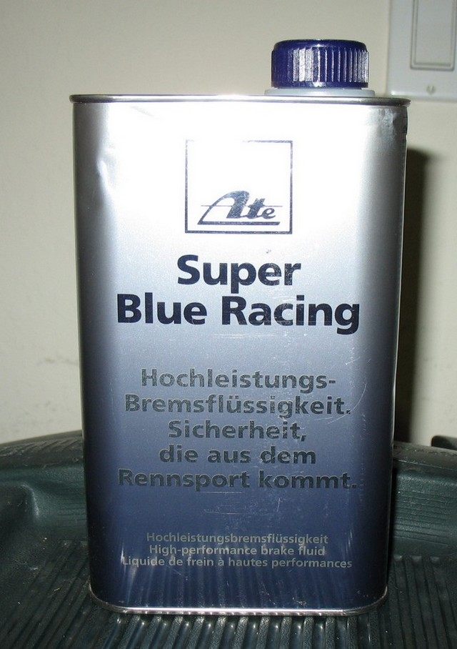
Another cause of brake fade is the brake fluid boiling in the brake caliper. This results in that horrible spongy, nasty pedal feel as you go careening off into the woods. This is caused by many things. Poor heat dissipation in the brake system can cause this (new rims can sometimes cause the airflow over the calipers to be reduced versus stock and actually decrease braking potential). Another cause is overheating of the brakes due to excessive use (too many hard stops in a row, riding the brakes, especially down hill). But arguably the most common cause is too much moisture in the brake system. No system is perfectly sealed and the brake system is no exception. Unfortunately, the nature of brake fluid is to absorb water. It's called hydroscopic. So over time, brake fluid gets contaminated with moisture, which lowers it's boiling point. There are two important methods to combat this. The first is to change/bleed your brakes often. The second is to choose a high quality brake fluid. On the back of every can of brake fluid sold in the US there are two numbers printed. The higher number is the dry boiling point, which is the point at which the brake fluid naturally boils (no moisture). The second is the most important and is called the wet boiling point. This is the point at which the fluid will boil with moisture present. I recommend the fluid with the highest wet boiling point you can afford. For me the best compromise was this:
Like the can says, this is Ate brake fluid. It doesn't have the highest wet boiling point available, but fluids with a higher wet boiling point can get seriously expensive. This has a dry boiling point of 536°F and a wet boiling point of 392°F. It also has the advantage of coming in two different colors, so when you bleed your brake system, you can keep bleeding until you see the new color coming out at each bleed point. You can alternate with each bleeding.
Rear Brakes
August 29, 2006
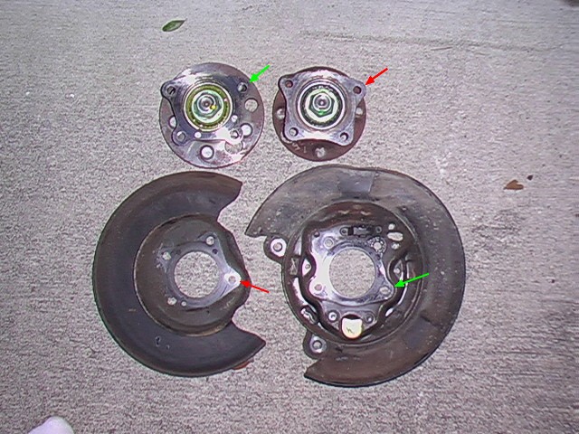
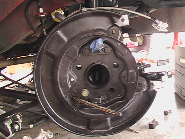
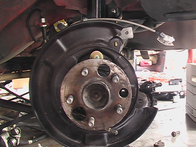
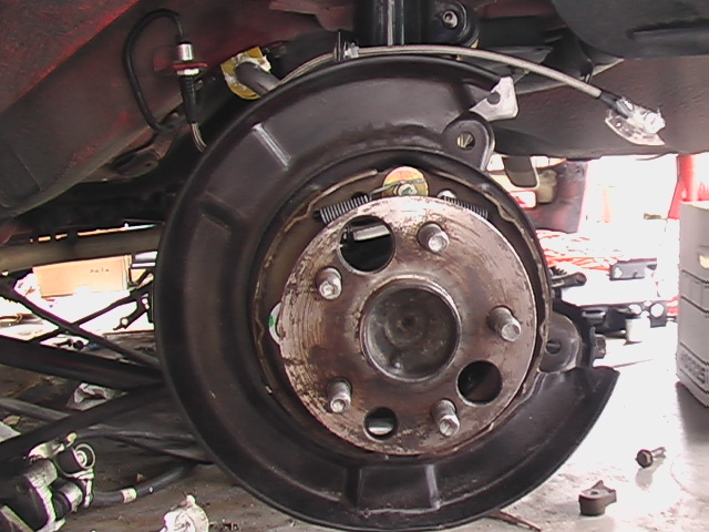
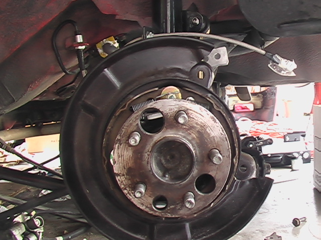
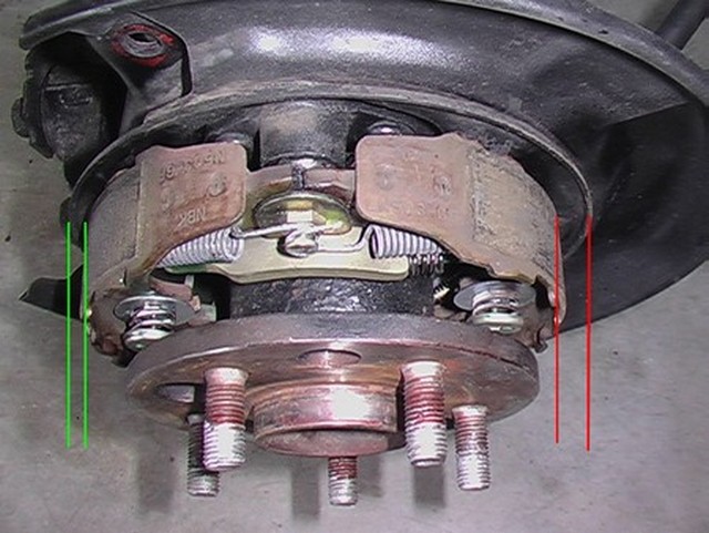
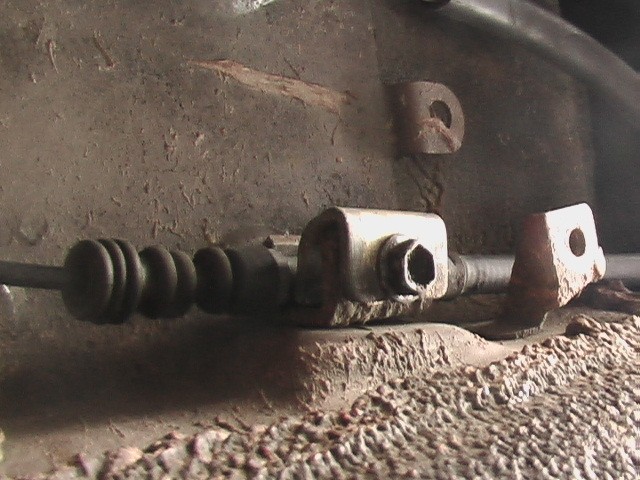
I kind of messed up this picture because the Corolla rear hub is on the right and it's dust shield is on the left. Oops. The green arrows go together and belong to the Celica and the red arrows are the Corolla. You can see that the Celica hubs are of a similar design but larger. Some other important things to note here are that because the Celica design has a drum brake inside the disk that operates as a parking/emergency brake, it needs this backing plate because some of the parts attach to it and so does the caliper. Also, the cut-out in the dust shield of the Corolla and Celica are on opposite sides. Finally, without the dust shield the hub won't seat agaist the upright assembly. There is a little lip that will keep it from sitting flat. So I figured I better use the mounting plate.
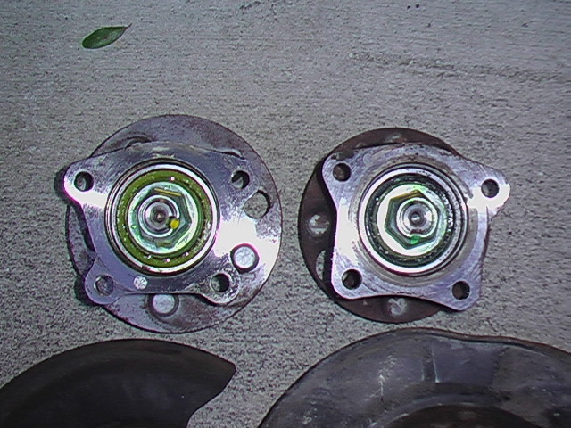
Here's a closer look at the hubs.
The fact that the hubs were different sizes actually became a problem. I had to choose between the Corolla hub and the Celica hub.
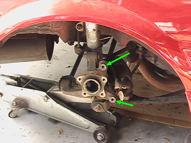
But look at the upright assembly on the car. Naturally I wanted the Celica hub because I wanted all of the other Celica parts to fit but the part on the car and the hub were a perfect match. In the end, I decided to have the Corolla housing opened up a little bit so that the Celica hub could be pressed into it. I took the parts to a machinist and essentially told him to measure the hole from the Celica hub housing and then open up the Corolla housing to that diameter. This way the Corolla hub bolts to the car, like always but it will accommodate the Celica 5 bolt hub and bearings.
I did do extensive research into a bearing that might have the correct dimensions without having to alter these parts. No luck, so this seemed like the best solution because it would bolt right up and allow me to purchase stock Celica parts for future replacement.
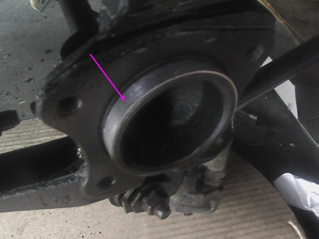
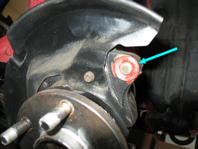
Unfortunately that wasn't all it took. Now that the hole in the Corolla hub had been opened up, it no longer rested on the little lip of the upright. Plus the backing plate was from a Celica, so the hole through the center was also larger. I didn't like this so I had a little ring machined to make up the difference in diameter between the Corolla and the Celica (purple arrow).
In the previous picture you can see the little ears (green arrows) on the Corolla upright where the caliper mounts. Well, they interfered with the Celica backing plate, so I had to cut them off.
There is also a little o-ring behind the ring I had machined. I think it keeps dust and dirt from getting to the rear wheel bearings. I don't think it is doing any good now.
And here you can see the difference between the Corolla and Celica rear disks. The unusually large center portion (the hat) is because, unlike the Corolla which uses the existing caliper as a parking brake, the Celica disk uses a separate drum brake housed within the disk, like I mentioned. When I first saw this on my old BMW, I thought it was pretty clever, but now I don't like it. I presume they do this because drum brakes are self energizing, meaning that when they are applied, the rotation of the drum causes the brakes to want to apply more. Also, it provides a measure of redundancy, because it operates as a completely separate system from the fronts and rears. Either way, I don't like it because it requires drum brake parts and the difficulties associated with changing them. But hey! I got larger brakes. I'm not complaining.
During the disassembly I noticed that one of my suspension members was bent, so I called around to junkyards to see if anyone had my Corolla there, but all I could find was a sedan version. So I drove down there to take a look. I brought my old one with me and compared the two. I was very happy to see that not only was it basically the same, but that it was lacking the caliper mounting bracket ears I was forced to cut off on the passenger side. Ah, a match made in heaven.
If you're smart, you're probably asking, "What's the catch?" and you'd be right. There was a small difference, but nothing that couldn't be overcome pretty easily.
In the above photo, you can see that there is a slight gap between the upright and the suspension member that attaches to it. This is not because the upright is different on the sedan than the coupe, but because the bushing that is pressed into it is different.
The coupe version has a bushing with an extended tube that fills this gap. So since I wasn't using this bushing anymore, I cut that tube off and created a couple of spacers to center the upright member, like this:
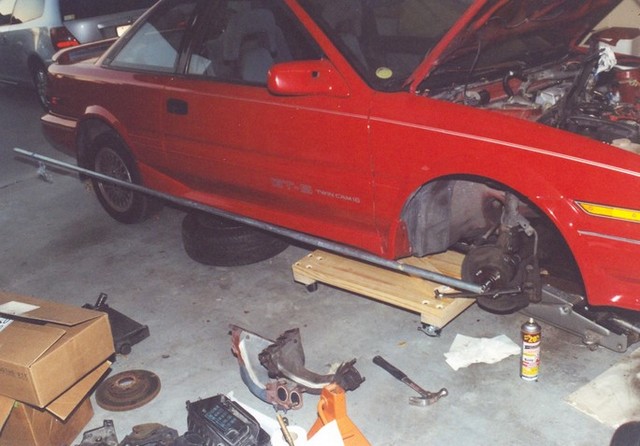
So with that all done, it was a matter of assembling the rear brakes. Here is a step by step photo guide to the order of the assembly on the driver's side.
Parking/Emergency Brake
December 4, 2005
It's difficult for me to explain what to do with the emergency brake but I'll try. First, the Corolla emergency brake cable will not work. Second, two cables go from the brakes to a sort of swivel plate. The Celica cables don't work with that swivel plate because things don't line up. Third, sourcing the cables is a problem.
In the picture to the left, you can see that the cable on the top is a little bit longer than the one on the bottom. The top one is the Corolla cable and the bottom is the Celica cable. It doesn't seem like very much difference, but look what happens when you try to use it.
The extra length pushes the brake shoe on the left out a little further than the one on the right, causing the brakes to apply.
VERY IMPORTANT NOTE. WHEN YOU GET PARTS FROM A JUNK YARD, RECORD THE VIN (Vehicle Identification Number) ON THE CAR YOU PULL THE PARTS FROM. I also recommend just getting the parking brake cable with the parts you buy. Even if it doesn't work for you, it will help with the design process. The dealer swore that there were three different parts for the parking brake cables on the exact same model of car. That is very strange to me, but he would not order all three unless I paid for them and he couldn't guarantee the right cables unless I had a VIN. I have never had that happen before, but it's better to remove all doubt.
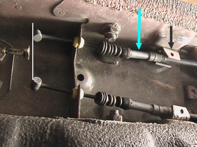
On the other end of the cable there is a pivot arm. It's not shown in the picture but it would sit where the white line is. With the cable from the Corolla installed the part on the cable where the blue arrow is, would line up with the part on the car where the black arrow is pointing. But as you can see the Celica cables don't quite fit.
Unable to get the welder under there, I had to come up with a different solution. The ends of the cable were more or less where they needed to be, but the cable needs to be held in place where the arrows are pointing.
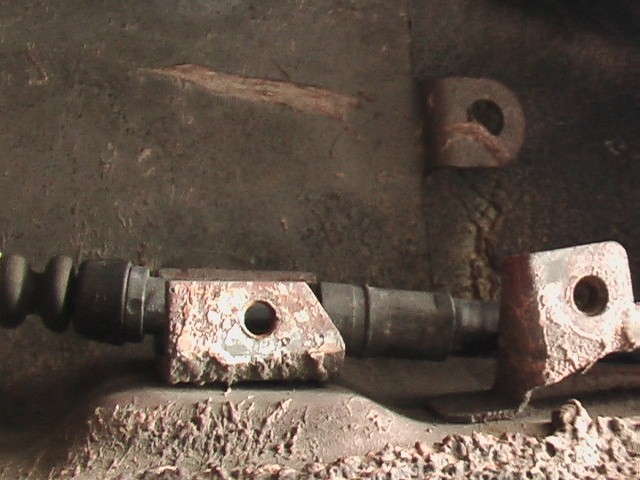
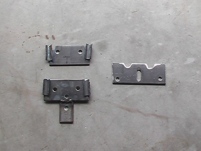
Here's how it's constructed. Normally the cable narrows as it passes through this little clip welded to the car.
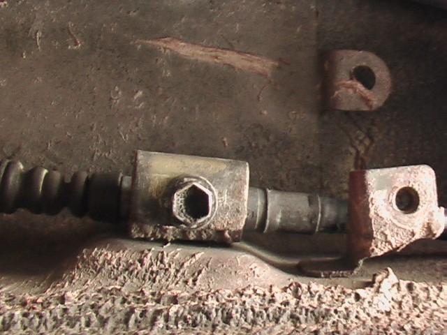
Then this extra little piece goes in and is bolted in place, capturing the cable at the narrow spot so that it can't move along its axis.
Here's another angle.
My solution was to move the clips that capture the cable to the new location of the Celica cables. Here are the pieces I fabbed up. Looks like overkill. I angled the tubular parts to keep the rubber boot on the cable from rubbing on a nearby bolt.
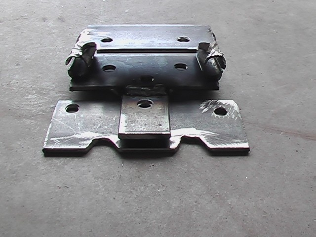
This is how it goes together. Obviously I did this with scrap material I had on hand. If you can put your car on a lift, it might be easier to cut off the original clips or make new ones and weld them into the new location on the car. I couldn't really do that so this is how I did it and it works well.
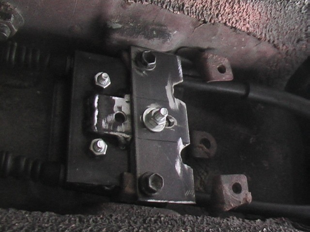
This is how it goes on.
This shot shows how the pivot arm works. It equalizes the tension in the left and right rear brake when the brake lever is pulled.
This is the whole mechanism installed. The single cable that goes from the pivot arm to the brake lever in the car is identical between the Corolla and the Celica. Strangely they have different part numbers.
Here's the finished product, more or less.
When I do the exhaust I will probably paint the bolts too, just to keep things from rusting.
Brake Lever
February 16, 2014
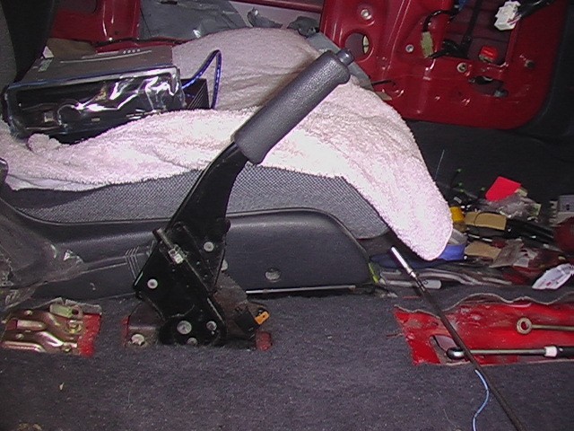
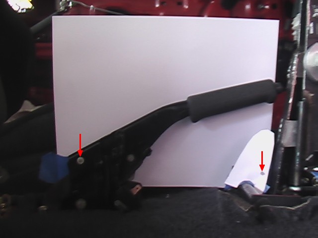
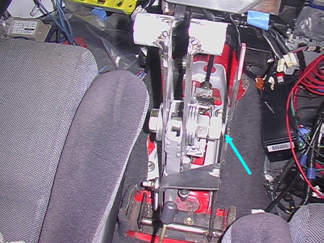
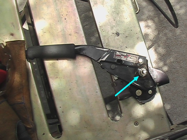
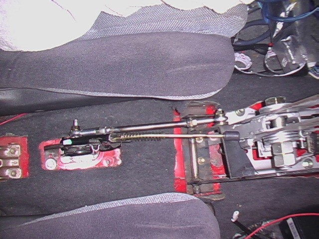
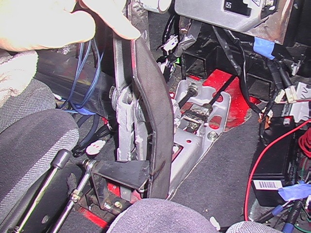
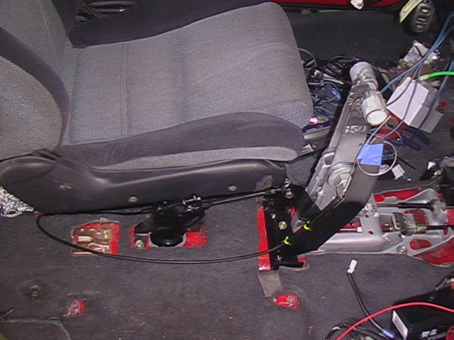
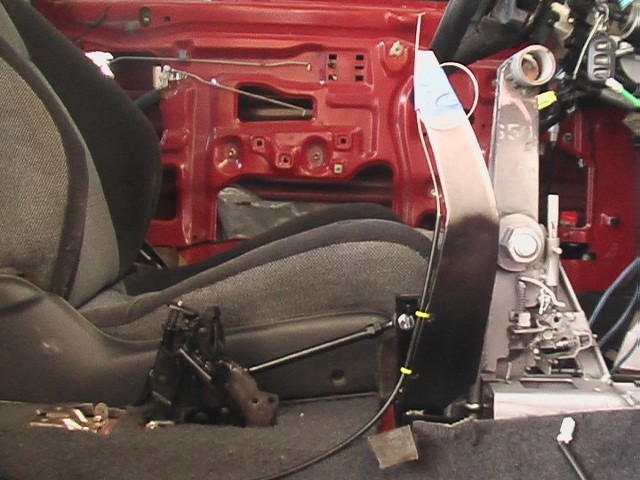
Now that I have a plan for the gear shift levers, I want to do something about matching the brake lever to the rest of the design. Here it is in the up position. What's important to look at here is the mechanism at the bottom.
Look how close the button comes to the gear shift levers, when the brake lever is down.
The center console that will mount over the top of this lever will double as my sub-woofer enclosure. I need as much volume as I can get for this so I prefer the brake lever take up as little room as possible. At the same time, reusing this mechanism saves me from having to design something.
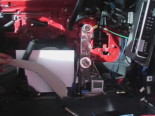
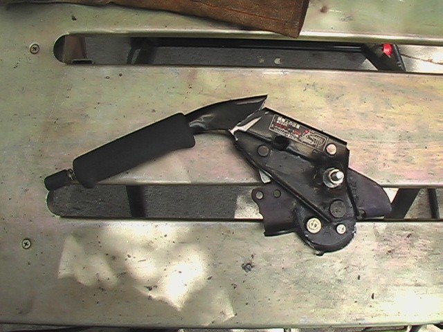
It appears to stick up about 4.5". That's more than I would prefer.
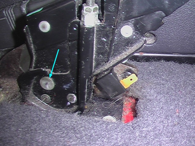
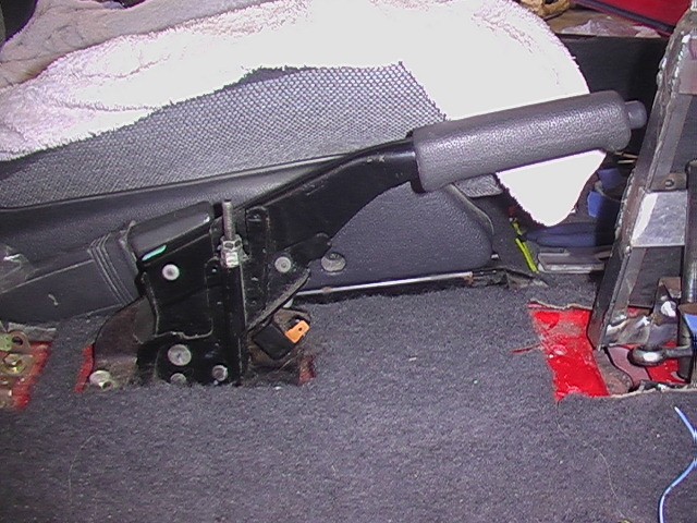
The whole lever rotates about the pin marked with the blue arrow.
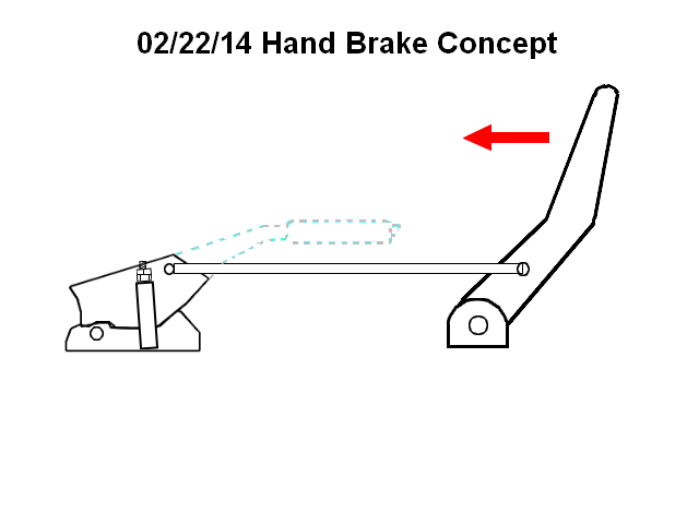
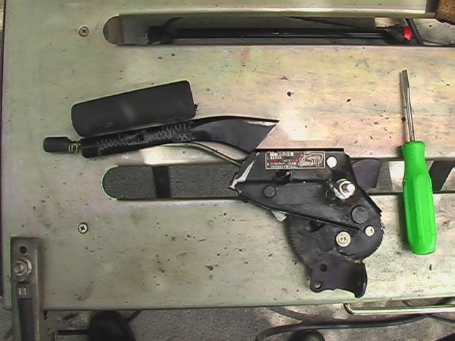
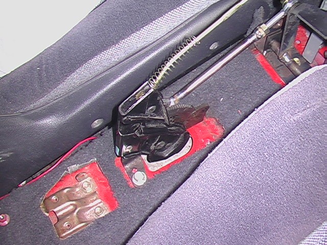
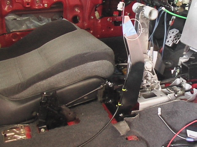
This is the plan for the hand brake lever. The portion outlined by the dotted line would be cut away, leaving the rest of the mechanism to function as it did before. The only problem with the set-up is the little button that releases the hand brake. I'm going to have to figure out how to make that functional in this situation.
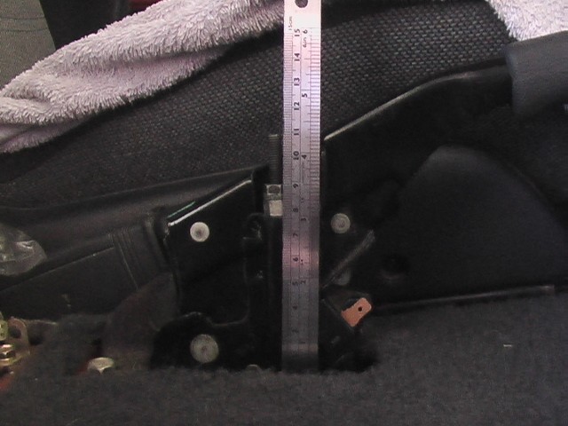
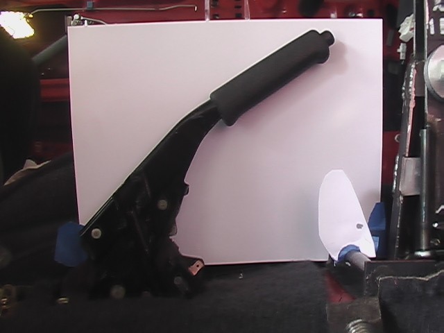
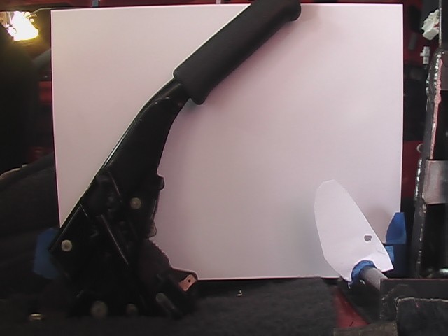
Here are some more pictures of the stock hand brake lever.
February 24, 2014
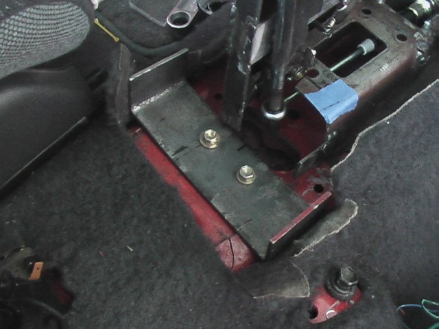
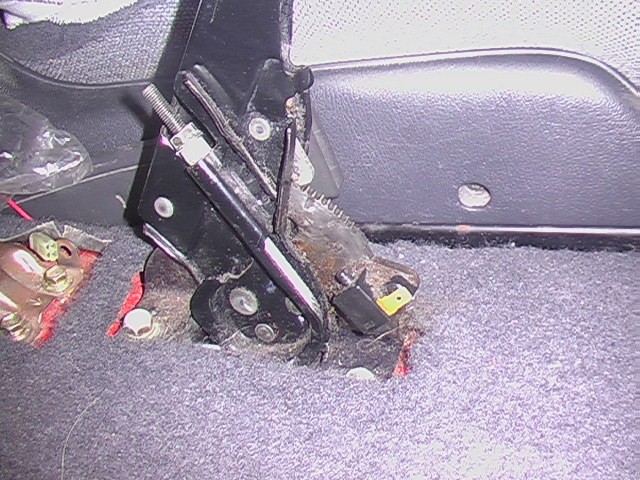
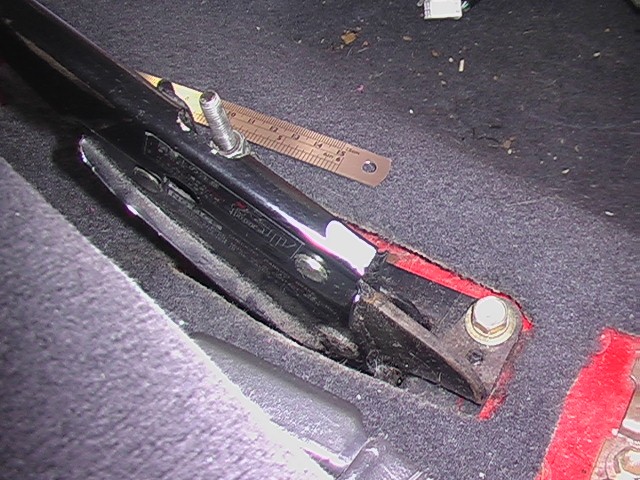
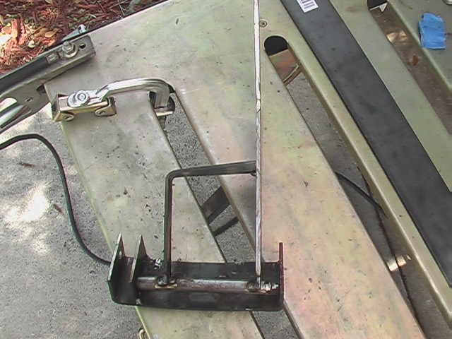
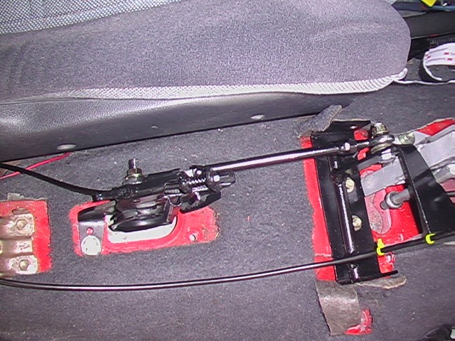
I knew I would need a sturdy pivot for the hand brake. Plus I thought I could use this bracket as a place to secure the center console. So I made this quite beefy. The problem is that the car is not flat in this spot, so I had to make the braket conform a little to the contours of the car.
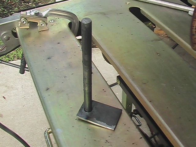
Normally I like to be able to take things apart, but this time I decided to make the pivot permanent, by sliding a tube over this rod I welded to the plate. In this picture I have greased the rod. Because I won't ever be able to access this again. Some of the grease burned off when I welded, but I think it will be fine. You can see how it's assembled in the next picture.
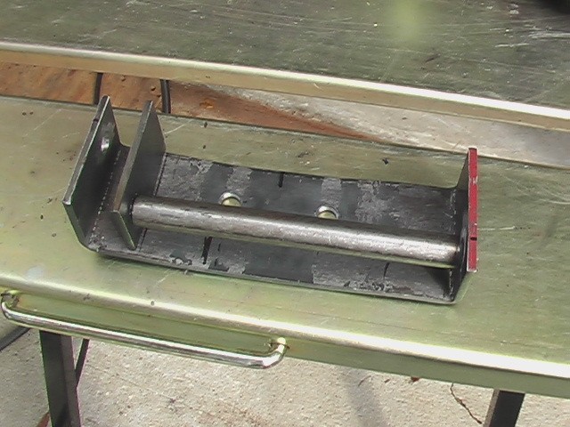
You can't tell from this picture, but you are not looking at the rod, but the tube I slid over the rod. The tube is captured on the ends by the plates. Everything is welded.
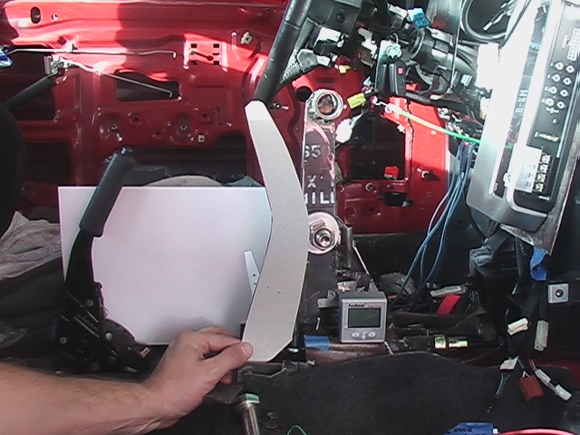
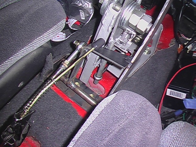
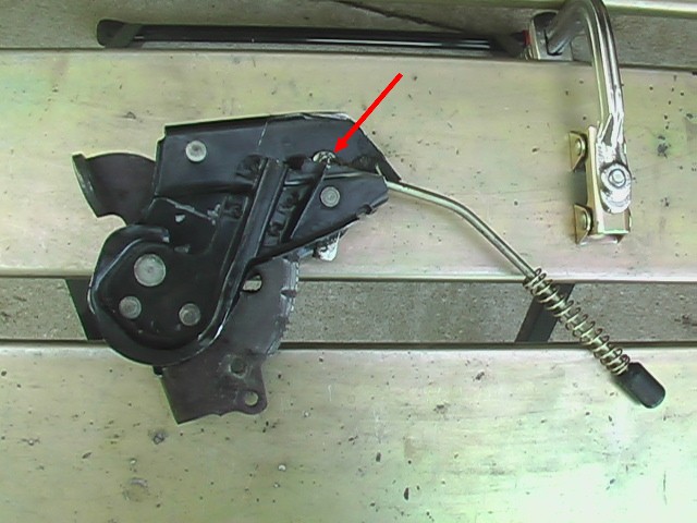
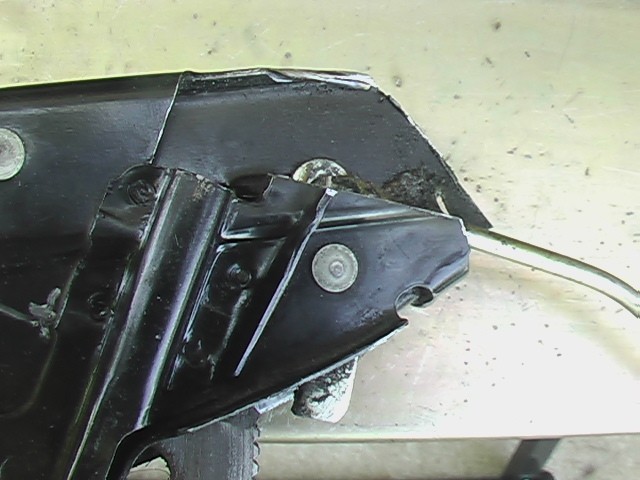
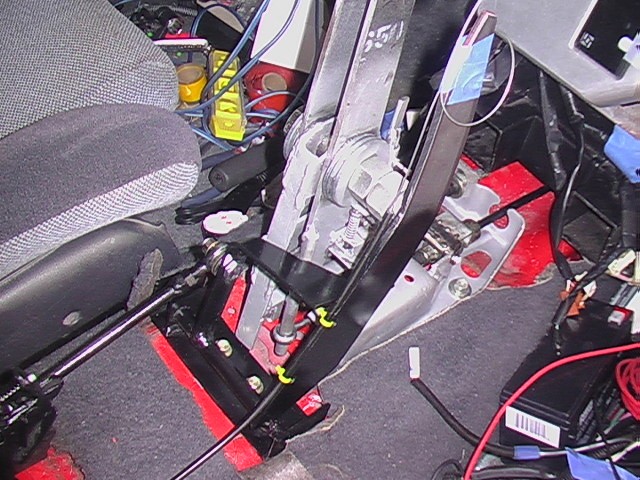
Next came the hard part of figuring out how to connect the new hand brake lever to the old one. Below are three pictures of a first shot at it. I considered a rod between the two pivot points marked by the red arrows. As the paper attached to the pivot point moves, so does the handle.
This looked good at first, but when I attached a mock-up lever in place. Look how far it moved.
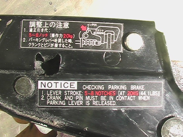
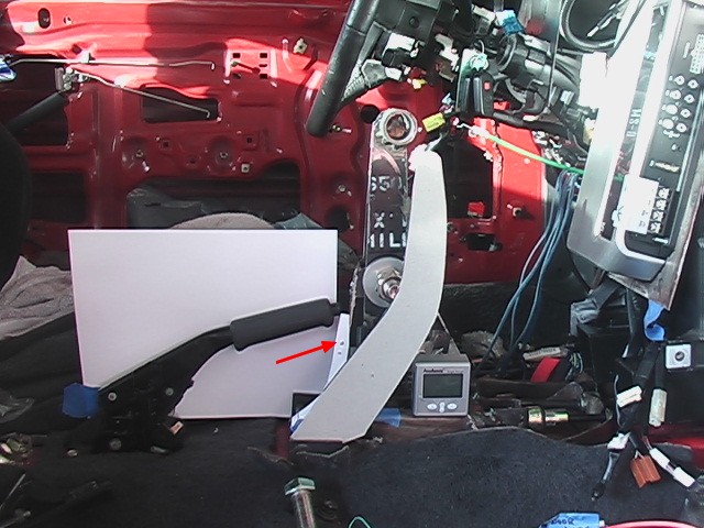
What I needed was more leverage on the new lever side for the same motion on the old lever side, like this. Incidentally, this is worst case on the old lever side. It is all the way up. It is printed on the lever that it is supposed to be engaged with only 8 clicks. Still, over time they go further and further back, so I figured I should look at the worst case.
This is the handle in roughly the disengaged position. The red arrow is where the rod would have to connect on the new lever to produce this motion. As you can see it is pretty high up. That means I have to check to see what kind of effort it would take to pull this hand brake.
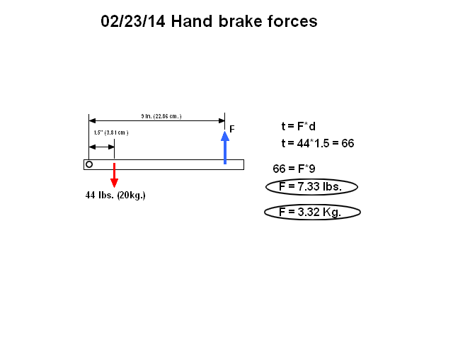
The sticker on the handle said 8 clicks with 20Kg force. That's 44 lbs of force. That seemed like a lot to me, so I figured it must be 44 lbs on the cable. If that was true, then I could make some calculations. The cable was 1.5" from the pivot point of the original hand brake lever. If the cable had a resistance of 44 lbs, then what force would it take to overcome that resistance? Torque = Force x distance. So as you can see that works out to 7.3 lbs of upward force. That seemed more like the effort required to apply the hand brake to me. Actually it seemed more like 10 to 12 lbs to me, but in this calculation I assumed only one point of force, whereas in real life a hand would cover most of the grip on the end of the handle. I think I would pull the lever up with the two fingers furthest from the pivot point, more than my others. Given that information and a ruler I decided on 9".
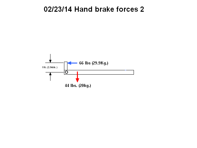
If I applied my force on the old handle about an inch above the pivot point, it would take 66 lbs of force. As you can see here.
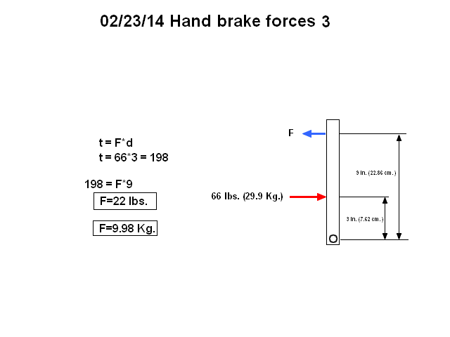
With the force on the new handle applied at 3" from it's pivot point and still needing to apply 66 lbs of force on the old handle, I calculated the force it would take applied at 9". It's just coincidental that the new handle also had about 9" of distance to the applied force. It looks like the total force needed would be 22 lbs. Not surprising, since the point where the force is applied is 3 times that of where it needs to be applied, it makes sense that it would take 3 times the effort (7.3 x 3 = 22). But I do get three times the travel. Or you could say that I need 66 lbs of force applied at 3" from the pivot point so to get that at three times the distance would only require a third of that (66/3 = 22). Either way, I think that 22 lbs of effort isn't too much. Plus I think the direction the force is applied is a bit more natural than the stock handbrake. Even if I'm off a bit, I think this should be fine. That means I'm going to go forward with these points in the handle design. These calculations are pretty simple, but I wanted to go through them, to convince myself that the new brake handle wouldn't be too hard to use. I hope I'm right.
May 14, 2014
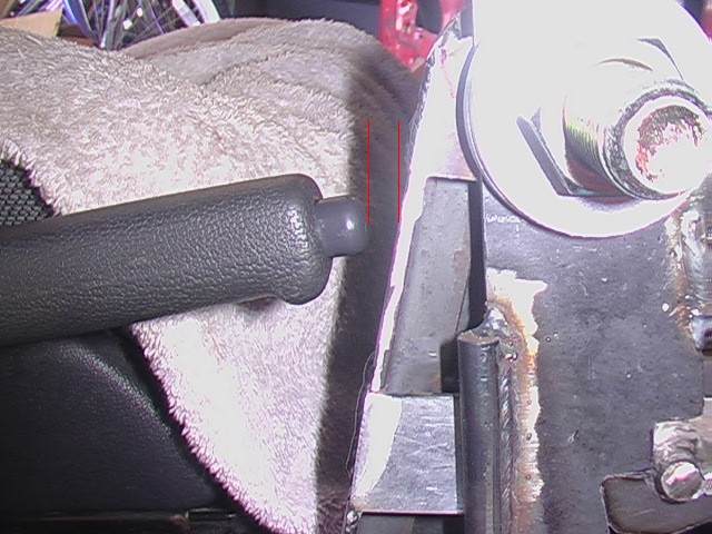
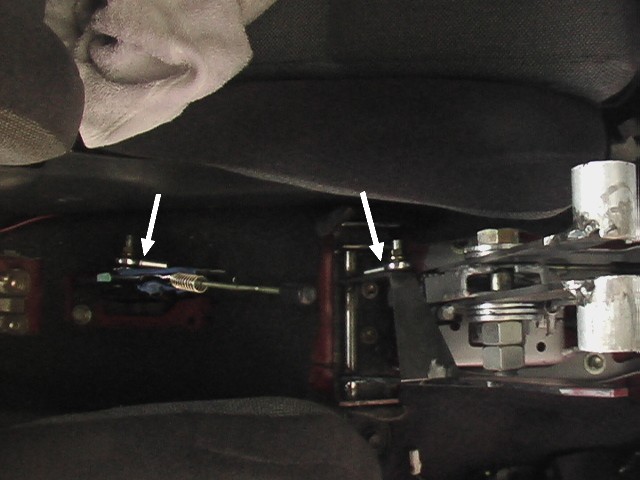
When I first welded the brake lever to the pivot point, I just tacked it in place and noticed it was pretty far to the right. So I reinstalled the passenger seat and sure enough the handle just dragged ever so slightly against it. I knew I would need extra room to include a center console but if I moved it to the left, it would interfere with the end of the bolt (blue arrow). I had no choice but to trim the end of the bolt off. I forgot to take a picture, but here's one after I moved it. It looks closer than it is.
I added this angled part to the lever so that I could have something in line with the old brake lever. It also adds quite a bit of strength. What makes me happy about this arrangement is how smoothly and quietly it moves.
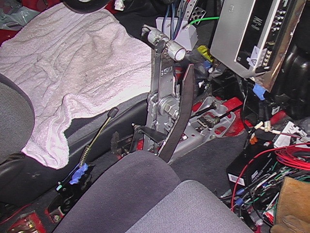
Here's another shot of it in the car. Like the shift levers, this one will be cut off so a machined handle can be installed.
Next I welded a bolt onto the side of the old brake lever in the location I calculated earlier(blue arrow).
Next I had to cut the end off. I hate messing up perfectly good stuff, but. . . no fear, right?
In order to get the end of the handle off, the grip had to be removed. It really cannot be removed by pulling. It is adhered to the metal arm quite well. I got mine off by cutting it along it's length and then prying it off with a screwdriver. You can see the glue left behind on the metal.
I put a bolt through my new brake lever bar and attached two Heim joints to them. Now I just need to connect them somehow and give it a pull. Unfortunately, I didn't have anything with the same thread at the Heim joints so I couldn't do this. I went to Home Depot, but they didn't have anything with that thread either. I hope I can find it at Ace Hardware. They have a pretty good selection of fasteners. So stay tuned.
May 17, 2014
I got the parts I needed and was able to connect the brake lever to the old brake mechanism.
I welded a bolt onto the end of a rod and threaded a Heim joint onto each end.
There is some adjustment if necessary.
Here, the lever is in it's normal position
Here, it is as far back as it can go. I like the amount of travel. Now for the hard part, figuring out how to make the release button work. I think it's the reverse lockout problem all over again.
May 18, 2014
I went out to the garage today and figured I was going to have a huge challenge that would keep me baffled for months again, but to my surprise my idea worked right away. In fact, I completed 3 tasks today and found myself trying to remember what was next. At least it was a beautiful day, 80 degrees F, sunny skies and a nice cool breeze. I'm guessing that will be the last nice day as things begin to get hot around here.
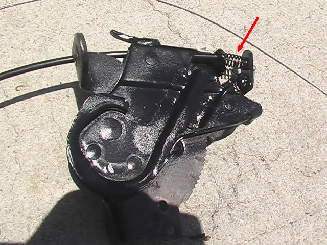
I started by cutting away enough of the metal to reveal the end of the little locking lever (red arrow) in the original hand brake.
Here's a closer look.
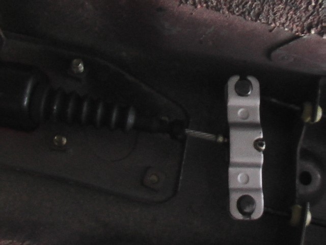
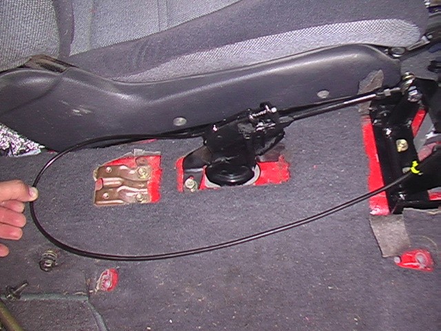
I didn't take too many pictures along the way, but what I wound up doing was using a bicycle cable I had in the garage. I installed a compression spring to keep tension on the locking lever, much like the original design. The bicycle cable runs through the spring and attaches to the locking lever. The cable routes to the new hand brake lever, where I will install a trigger that releases the brake. Simple and effective. In this picture I've already painted everything.
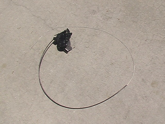
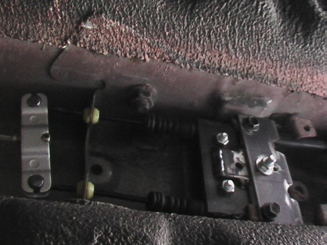
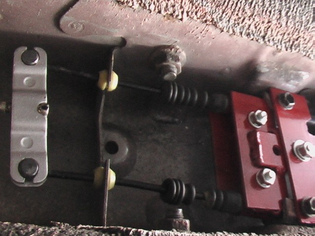
In this picture you can see the cable. It has to be longer than you think because it needs to have a fairly large loop in it, to function properly and it makes a U-turn to get where it is going. You can see that in the following pictures.
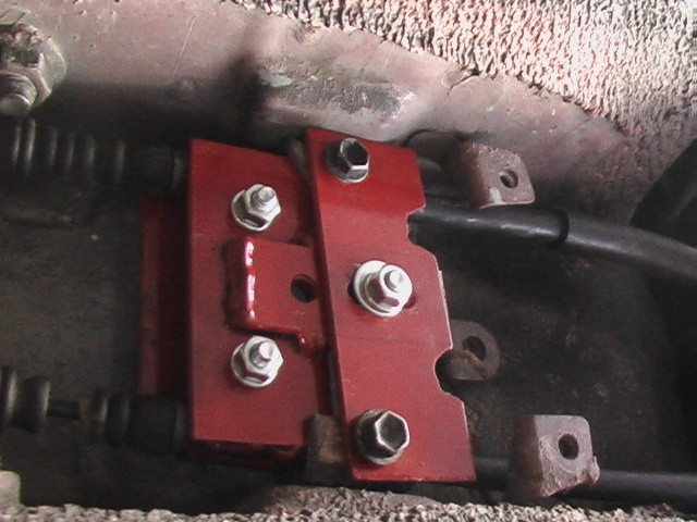
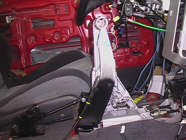
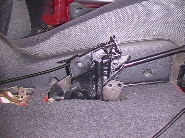
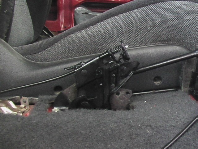
Here are a bunch of pictures of it installed. This is as far as I can go with the brake lever and the shift levers until I get parts machined, to make it look pretty. Nothing you see in these pictures will be seen when I am finished.
To be continued. . . .