
Mechanical
Motor Mounts
December 11, 2010
It should be obvious to you, if you are capable of doing an engine swap, that this engine will not just bolt right into the Corolla. It was never meant to go there. However, a beautiful thing is that the transmission WILL bolt right in! This is very important because using the transmission to position the engine means I don't have to figure out how to mount the engine myself. I can tell you from experience, when the engine is hanging from the engine hoist and I can move it back, move it forward, turn it this way, turn it that way, it can be very difficult to tell where to put an engine, especially if after I do it, I then figure out that there is no room now for the radiator or the exhaust manifold or something. This is a huge advantage.
Next, I have to mention that this is the way I did it. There are probably a thousand ways to do it and I'm not pretending that my way is even the best. I merely fumbled my way through, made a few mistakes, corrected them and moved on. Also, my goal was to install the engine with the stock computer and almost the entire system in stock form.
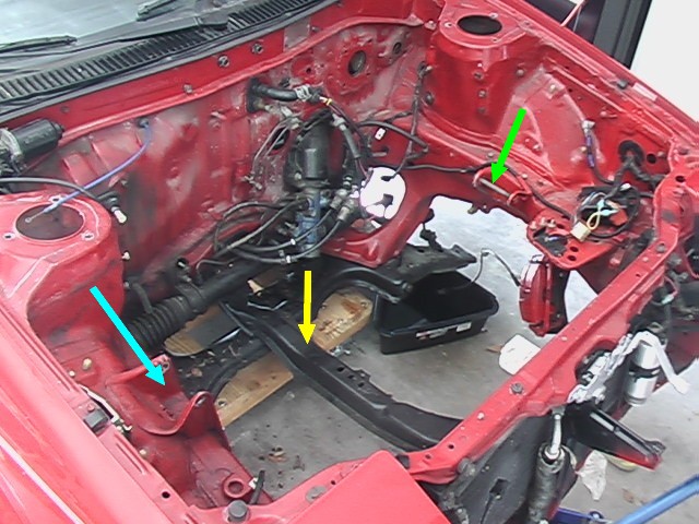
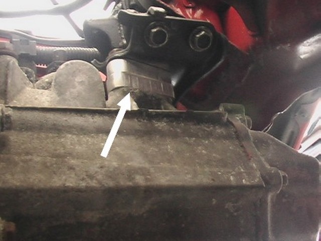
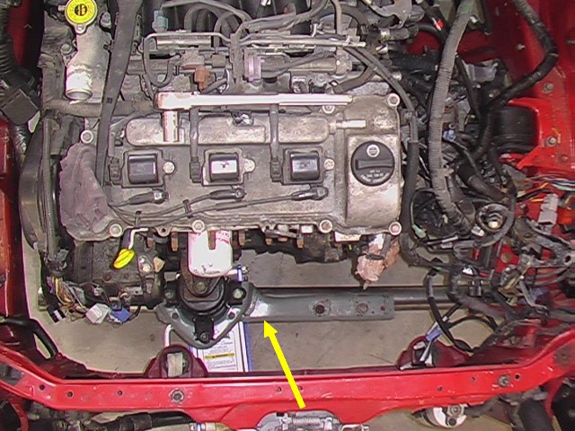
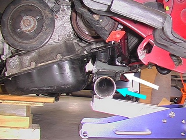
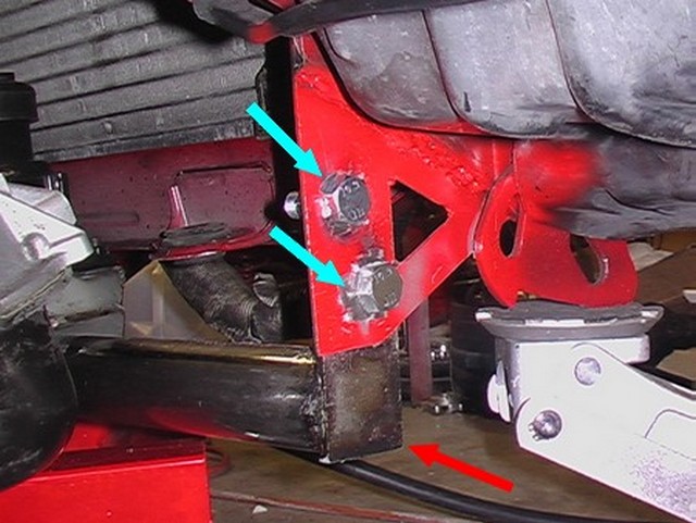
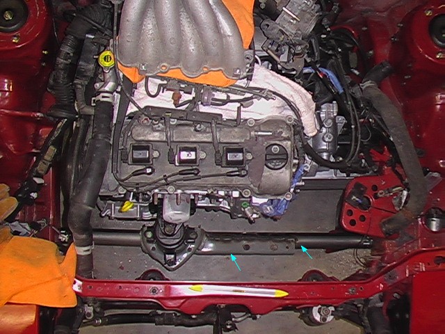
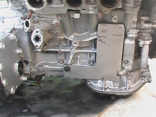
The first thing that should be mentioned, is that the engine support in the Corolla(yellow arrow) is not in the Solara. Instead there is a square subframe that runs all around the bottom of the engine compartment. The exhaust runs under the 1mzfe engine right where this support goes. Don't forget this is a V6 engine and has two exhaust manifolds. I don't see any other place to route the exhaust except where Toyota has run it. That means, this support has to go! But that also means that a primary support method for the Corolla has gone away. It is up to the engine swapper, me, to provide sufficient support.
The green arrow points to the transmission mount. Because I am using the E153 transmission and an E58 used to bolt into the Corolla, this transmission mount WILL work!
The motor mount by the blue arrow is not used. There is a chance it could be used on the stock engine, but I am superchaging the engine and it just won't work.
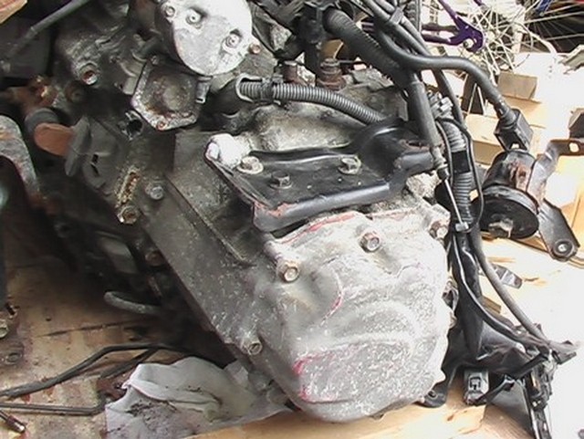
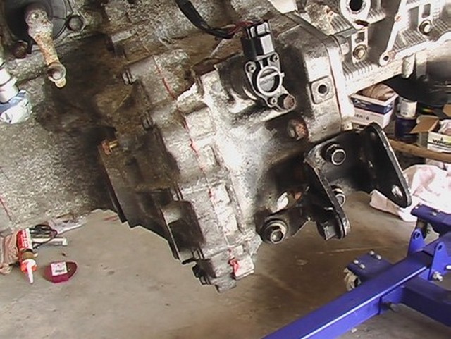
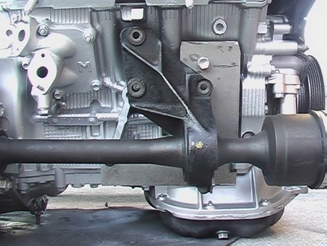
The Solara Transmission is supported from underneath. It is supported from above on the Corolla. Because the transmission case is virtually the same, the bracket that supported the transmission in the Corolla can just be bolted on. It is the black bracket dead center of this picture.
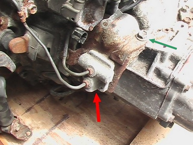
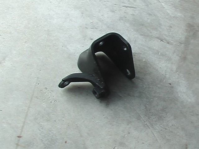
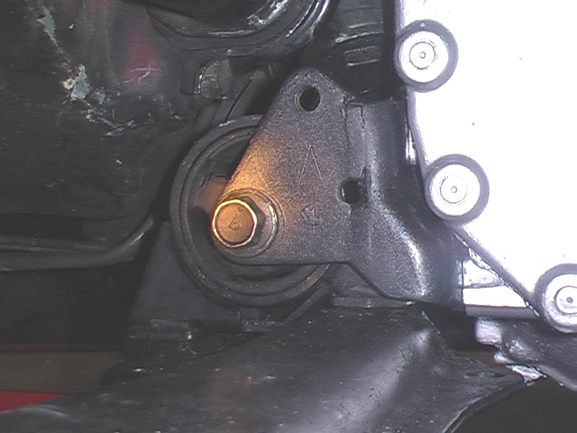
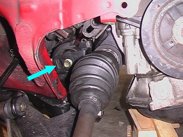
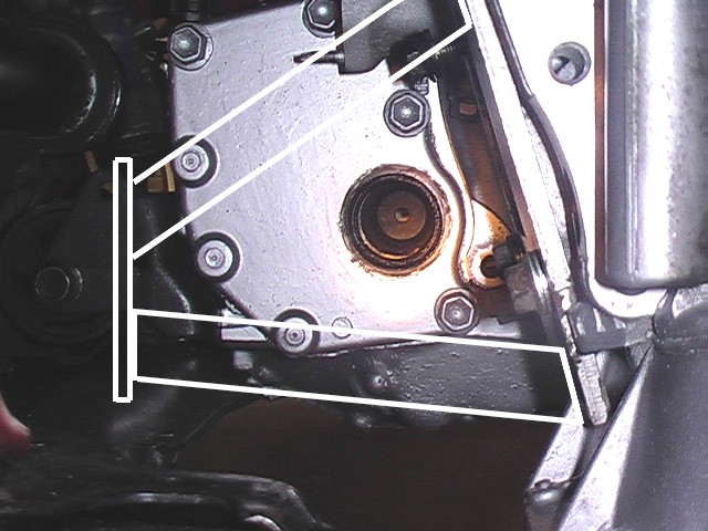
In order to attach the bracket, this clutch thingy must be removed, because the bolt where the green arrow points is used. I plan to use this clutch thing, so I will have to figure out another way to mount it. I don't really know what this thing is. I think it's called a clutch dampener or something like that. I think it makes the clutch pedal motion smoother, for all those delicate Solara owners. Remember the Solara wasn't exactly a sporty car. If you know for sure what purpose this serves, drop me an email.
What is certain in this swap is that there IS interference with the hood. I handled this in two ways. First, I lowered the engine in the car. This helped, but did not solve the problem. Then I cut away part of the ribbing on the bottom of the hood to make clearance. It should be noted that as of February 8, 2014, I have not yet cut away those ribs. But at this point, I only have about 3/4" interference, so I expect it to work.
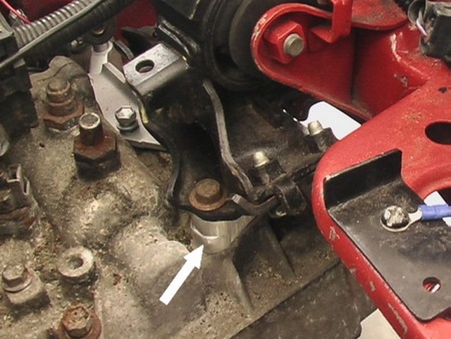
In this picture you can see that I've added two 1/2" shims (white arrow) to space the engine down by 1" in the car. THIS DOES NOT WORK! This caused interference between the drive shafts and the suspension. The most I could lower the engine was 1/2". So I removed one shim.
Here's another shot of the two shims.
You might be able to get away without lowering the engine at all. Maybe if you cut away part of a rib on the underside of the hood, it will fit. I don't know. You are on your own on this one. But because I did lower the engine, I had to modify the bottom transmission mount. I have to say that I hate this transmission mount. It's nearly impossible to get to and causes me headaches every time I have to install or remove the engine. I hate it! That said, if the engine goes down half an inch, the bolt that goes through this mount will be 1/2" too low. So I removed the mount and modified it to work. I didn't think about this before. If I had it to do all over, I would probably try to fit the hood without lowering the engine to save myself the work. But I didn't do that. So here we go!
July 19, 2010
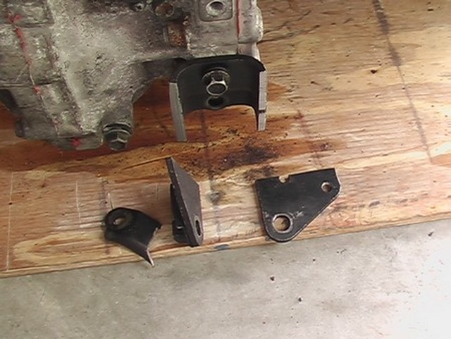
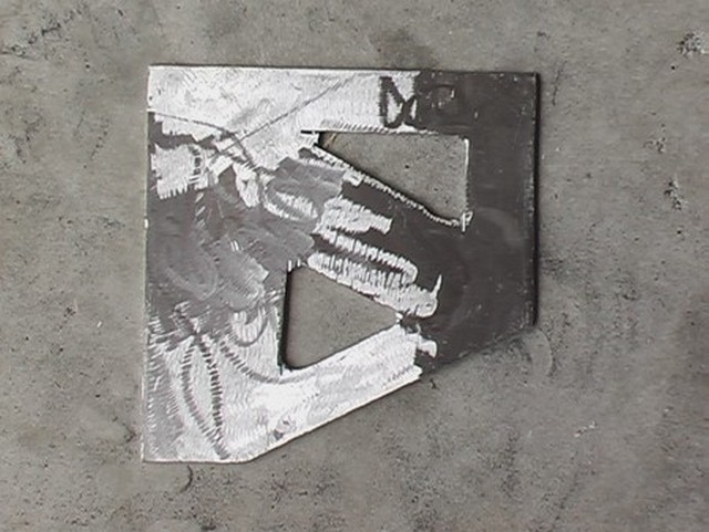
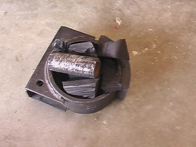
Since I was going to use the dreaded rear transmission mount, I took it to the band saw and tortured it to within an inch of its life. Or rather half an inch of it's life. Here's what it looked like at that point.
It felt good to cut that thing into pieces. But after that it was time to weld it up. The idea was to raise the three pieces on the floor up half an inch so that when the engine is mounted in the car it would be lower by half an inch. This was about as far as I could go.
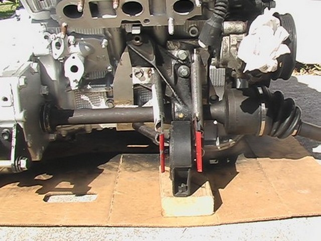
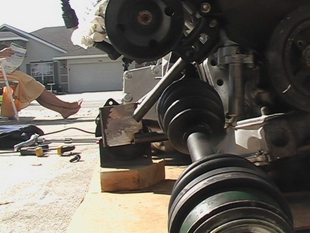
I showed this in the Swap section of this website, but I'll show it here again. You can see that the inboard CV joints come very close to the suspension with 1/2" drop. Any more and the two hit. I didn't want to modify the suspension, so I stopped at half an inch.
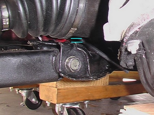
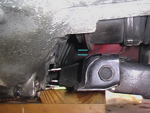
See the blue lines? When a car is driven hard, things flex. It may seem like this is plenty of space and I think it is, but I've seen slow motion video of things flexing and it's amazing how far they can go. I hope this is ok.
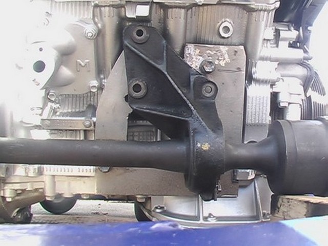
And here it is, in place.
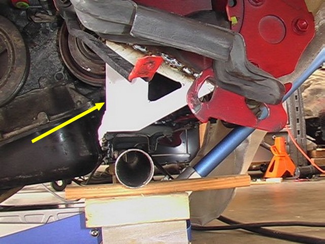
That covered the transmission mounts. I then had to move on to the motor mounts. Not one motor mount would work. On the Solara, the motor was supported in the front of the car. The Corolla didn't have anything at the front to support the engine, so I installed one. Here you can see I am mounting a thick walled tube from one side of the car to the other. I have cut out the part of the support from the Solara (yellow arrow) so that the engine can use the same motor mounts that it used in the Solara. I'm just lining things up here. It was pretty easy. All I had to do is bolt the motor mount to the engine with the little piece of support attached and it held itself in place while I tacked it in place with the welder.
Here's a side view. The blue arrow points at the 2" diameter tube and the white arrow points at the piece of the Solara support that I chopped out of the donor car.
Why 2" you ask? Did you do a complex calculation to determine the stresses, you ask? I'm glad you asked. The answer is that I had a piece of 2" pipe in my garage. How often does that drive a decision, I wonder?
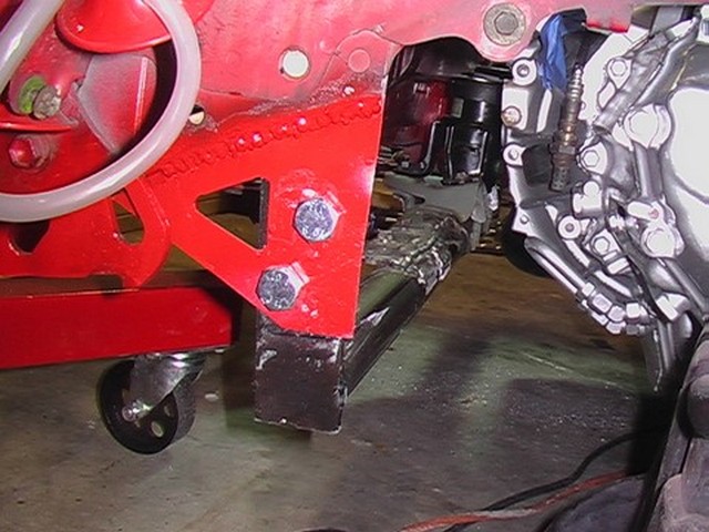
As you can see from the picture above, there is no place to mount the crossmember. It's just supported by the floor jack. So I made two of these braces to attach the cross member. These get welded to the car, but the cross member itself will be bolted to it, so that it can be removed to work on the car.
Here they are installed on the car (yellow arrow). It was very difficult to get in there to weld.
These brackets are very stiff, but I'm still concerned about their ability to hold the engine in place with side to side movement, so I have plans to add more bracing. I haven't done that yet, so stay tuned.
Next I had to weld brackets on the ends of the 2" tube so that I could bolt it into the car.
I used the jack to position the engine and then I match drilled four holes and installed the cross member.
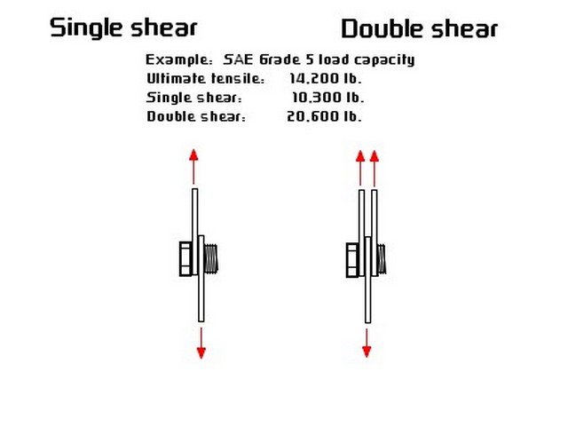
I mentioned that it bothered me that this support might move around under hard side load. It also bothers me that the bolts are in single shear. Whenever possible it is best to place things in double shear. This graphic shows why.
I will try to replace the original Corolla engine support after the exhaust is done. That will tie this cross member into the front of the car and hopefully add extra lateral stiffness.
Here's the driver's side (left side for you Aussies).
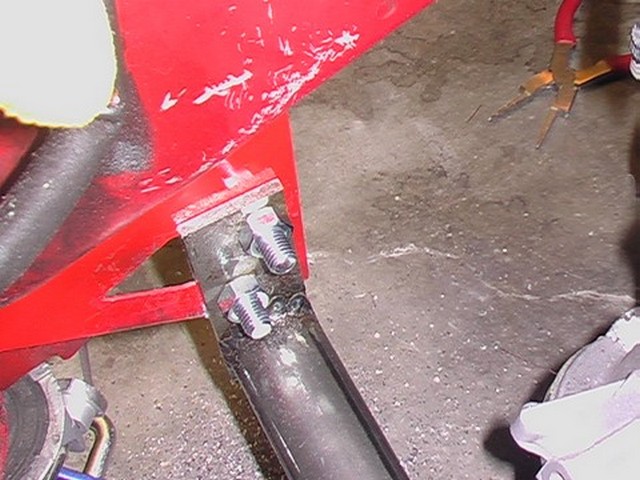
Here's another shot from above. Currently this bar is clear coated to keep it from rusting, but ultimately I will use lock washers on the bolts and have the bar painted with the car. This is also the driver's side (left side for you Brits).
Here's another shot from the top. The two parts marked by blue arrows are welded together.
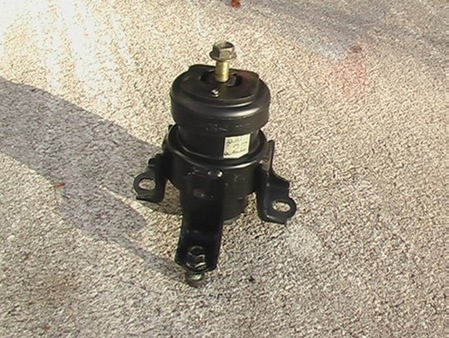
I cleaned up the Solara front motor mount. It was pretty nasty.
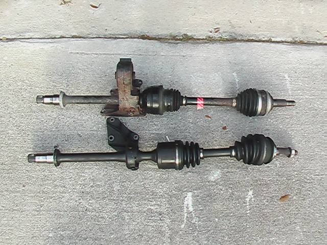
Next up was some kind of support for the rear. This was going to be the hard one. In this picture you can see how Toyota uses a center bearing on their right side drive shafts. Well, in the case of the Solara, this bearing pulls double duty as a rear engine support. Since this was one of the main supports for the engine, I decided to make a mount that would bolt to the engine in the same location. My mount fits around the drive shaft and does not support it, but it was still a major PITA. It's important to note that this area is tight. This motor mount has to support a lot of the weight of the engine. It has to be built in a way to allow the drive shaft to pass through it, yet be removeable. I have to be able to get tools in there. It is very difficult. Again, there are probably many ways to do this. This is just my way.
I used a front motor mount from the Corolla as a rear mount. This motor mount was already bad, so after consideration, I decided to pour my own.
This is where it goes.
As usual, the first step was to do some research.
I used a Shore D 70 hardness for the rubber. Online I found something that indicated that a shore of 65 was stock, but that 95 was too stiff and would cause vibration and noise in the cabin, so I opted for 70. It does feel quite a bit like stock when I press on it, but now the whole space is filled with material. We'll see how this works.
Tearing the old motor mount apart was tough. The rubber was very durable. I had to use a hack saw to get it apart. You can see in this picture that I roughed up the metal guide where the bolt goes. I was hoping this would make the rubber adhere better.
I bought the rubber at a place called "Smooth-on." Look them up on the net. Their products are excellent and very expensive.
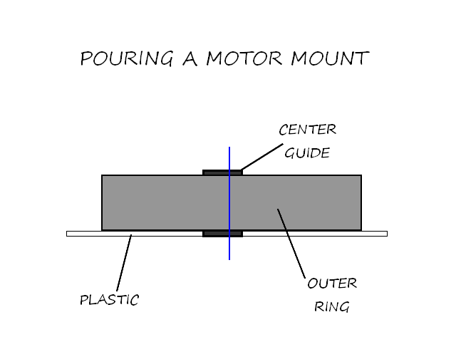
I placed the center guide a little bit high, because I assumed it would center with the weight of the engine on it. Normally this isn't important, but my motor was dangerously close to hitting on the car already, I thought this might help.
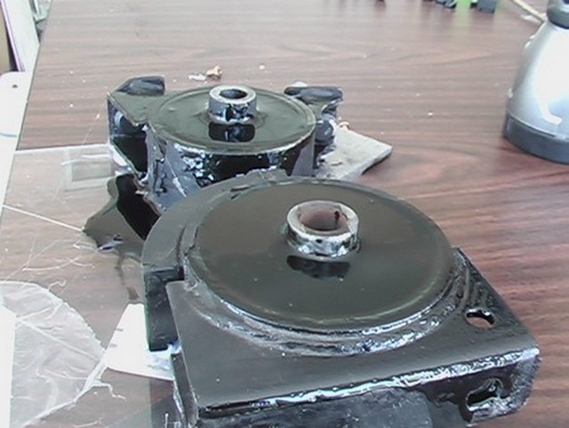
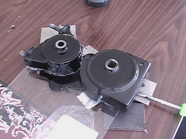
I drilled a hole in the clear plastic part to allow the center guide to be centered on the outer ring. I sealed up around the edges and poured the rubber. I also poured the rear motor mount, but I didn't tear it apart. I just poured over the rubber that was there. So even if it falls apart, it shouldn't matter. The old mount is still there.
I started with a very sturdy plate. I think this is about 1/4" thick plate steel. I then started forming it around the features on the engine, grinding down the edges as necessary.
I had to check the drive shaft on occasion to make sure things were going well.

This is how the motor mount will bolt to the engine.
And another check of the drive shaft. But there is a problem. The top hole of the drive shaft bearing is off the top of the plate. The plate cannot be extended because the engine block is in the way. Also, one of the holes in the motor mount is blocked by the drive shaft.
I had to install the motor to find the proper location of the motor mount. When I did this, I accidentally put a lot of weight on the drive shaft. I might have messed something up. Let's hope not. Here I have sketched up the idea for the motor mount.
May 7, 2011
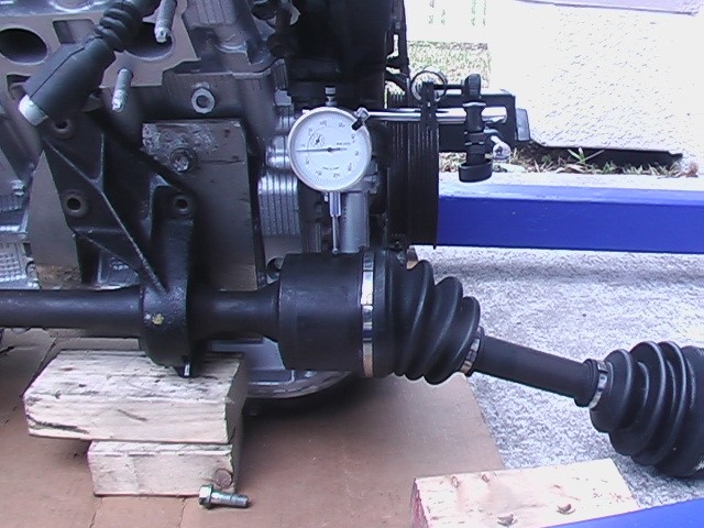
When I drilled the holes for the drive shaft, I wanted to make sure I didn't put a permanent stress on the shaft, so I put a gauge on it and lifted it up. Then I pushed it down. I repeated this in the left and right direction and placed the shaft in the middle of the measurements before match drilling the motor mount.
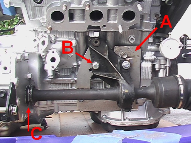
The adapter plate is bolted to the holes that the original Solara drive shaft/motor mount bolted to. I could only use 3 of the 4 holes however, because the shaft blockage. You can see the hole in the plate near B. The bolt at B, is used to secure the motor mount. This is important because it means that the motor mount cannot be installed independently from the drive shaft. There just weren't that many ways of doing this. The dust cover at C can be pushed toward the differential to make that gap smaller.
Then I started on the actual motor mount (as opposed to the adapter plate on the motor).
I made a V shaped support that bolted to the adapter plate around the shaft. It's not real pretty, but it will get the job done. The motor mount I poured rubber in before is at the location I measured with the engine in the car.
Next I added the bottom piece. The idea was to make a triangle.
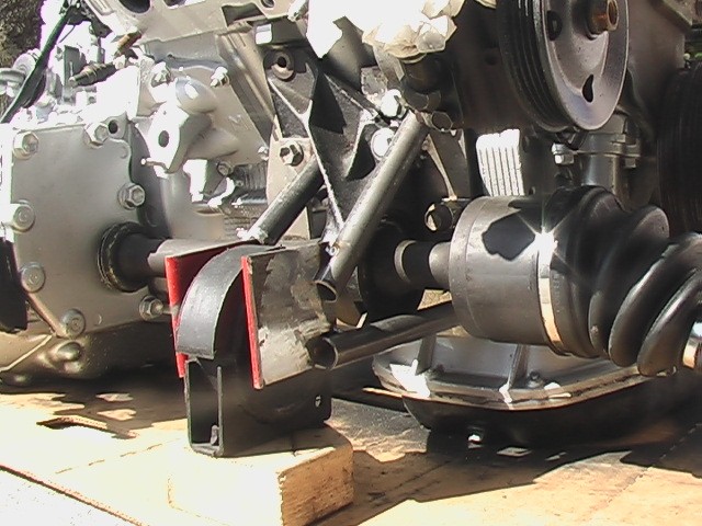
I repeated this on the outboard side.
This is what it looked like from head on.
And another shot from the side.
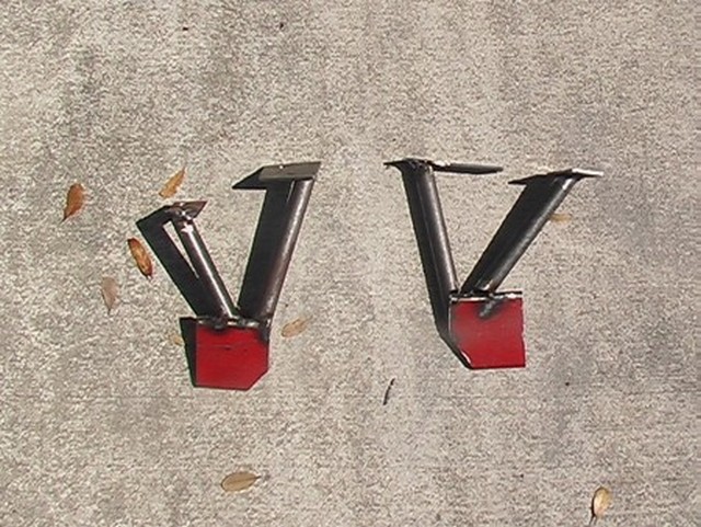
This is what they look like out of the car.
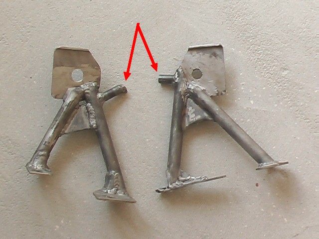
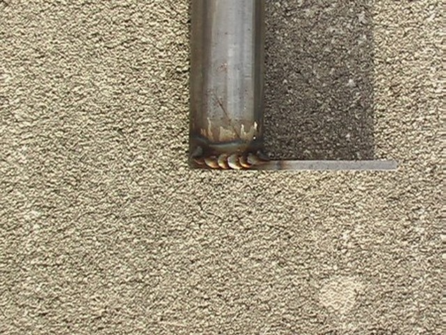
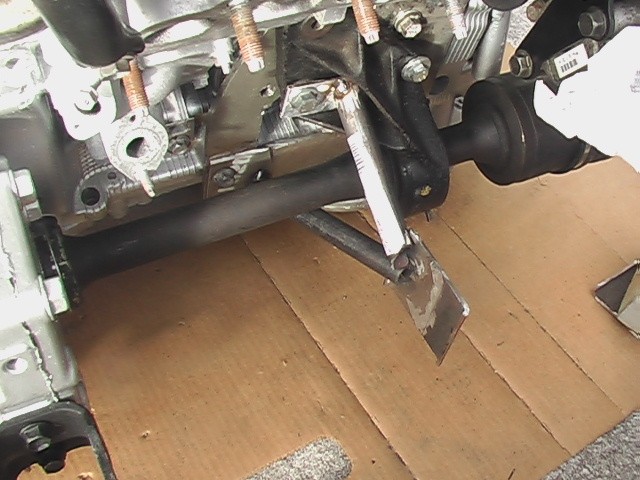
Finally I added these prongs to the mount. I call them safety fangs. The idea is, if the rubber in the motor mount gives too much, these teeth will hit on the frame of the car first, preventing the drive shafts from contacting the suspension and getting messed up.
And that was it for the motor mounts. From that point on, the engine has been in the car!
I did have to write a little procedure to remind myself of how to install and remove the motor mount/drive shaft. It has to be done in just the right order and it is tight in there.